Chapter 1: Preface and how to use this book¶
1.1 Why this book exists¶
Imagine this: the build finishes without an error, you prepare the image as instructed, and the board gives you nothing. No Linux prompt. No useful serial message. The files on the host look convincing, but you cannot yet tell whether the processor reached your code.
If you have brought up a microcontroller board, you already have a way to approach that silence. Follow reset to startup, startup to main(), and main() to the GPIO register. There may be a mistake somewhere, but the path is small enough to inspect. On an embedded Linux board, several programs run before your application gets a turn. Memory must be prepared, images must be loaded, and hardware must be described. Which of those steps did the board actually reach?
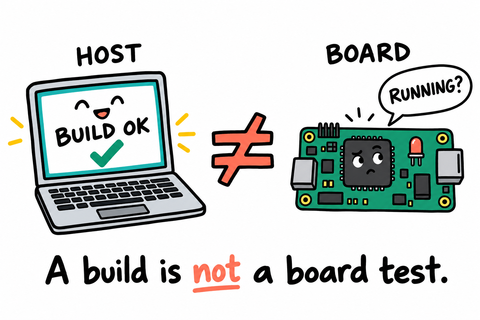
The laptop is pleased with itself. We still need an answer from the board. A clean build checks the host’s work. A response from our program, such as an LED change or a printed message, tells us it ran on the board.¶
A vendor board-support package, usually shortened to BSP, can give you a working system quickly. Install its tools, build an image, write an SD card, and you may have a Linux prompt. That is a useful starting point. The harder moment comes when you change the design: a different DDR chip, a UART on different pins, a board that no longer matches the supplied image. Now you need to know which setting belongs to the bootloader, which belongs to Linux, and which assumption came from the old hardware.
This book follows those questions on the i.MX6ULL. The first example is modest: an LED controlled by a program small enough to follow from its first instruction. Startup code, memory layout, and the Boot ROM’s header each have a job. Understanding those jobs matters more than reproducing the listing.
The same board then takes us further. A page table changes what an address means. A device tree describes hardware to Linux. U-Boot prepares a handoff, and a root filesystem supplies the programs that run afterward. Even when the software becomes large, we keep asking who owns a resource, what an interface promises, and which assumption lets the next layer work.
Implementation tools, including AI assistants, can help produce code. They do not choose the right failure boundary, establish a board’s wiring, or turn an unchecked assumption into evidence. The aim here is to understand a design well enough to choose it, explain it, and assess an implementation of it.
Buildroot enters in Chapter 35, toolchain construction in Chapter 122, Yocto in Chapter 123, and secure boot in Chapter 124. Their inputs make more sense once the pieces and their responsibilities are clear. A large build may still fail. The useful difference is knowing which layer to investigate instead of starting over and hoping.
1.2 Who this book is for¶
If you can read C, find a register in a reference manual, and follow a signal through a schematic, you have the starting point this book needs. Experience with a Cortex-M part, such as an STM32, gives us something familiar to return to when the Cortex-A7 behaves differently.
Linux experience is not required. The terminal may be new to you; the hardware is not. Perhaps you have built a vendor image but still cannot explain why the directory contains both vmlinux and zImage. You do not need to settle that question before opening Chapter 2. We will meet those files when we have a reason to inspect them.
Chapter 3 uses a host workspace to explain the build environment. When a command appears, its important consequence is what changes: a file, this terminal’s environment, or a persistent host setting. Commands illustrate those boundaries rather than form assignments to complete before reading on.
You can read the architecture without connecting a board. The worked hardware references are:
The Point Atom MINI v2.2 baseboard and its supplied core-board schematic. Another fitted revision may have different wiring and components.
The matching baseboard/core schematics and the supplier’s power instructions for that combination. The schematics supplied with this book are not a validated power-connection guide. Obtain that guide from the board supplier before attaching a supply, USB cable, or adapter.
The x86_64 Linux host model described in Chapter 3. Host paths, target addresses and device names belong to different systems.
If you independently explore an example on hardware, the actual assembly, documented supply, measurement equipment and cable arrangement must be established first. Storage, JTAG and peripheral add-ons are not reading prerequisites. Explanatory code is not permission to write a disk, change a rail or program a fuse.
1.3 What “raw” means in this book¶
Here, “raw” means being able to point to the thing that did the work. Which compiler produced the instructions? Which file described where they belong in memory? Which header told the chip where to begin? We start with two official prebuilt Arm compilers, one for bare metal and one for Linux. They stay in the project directory, and we choose between them explicitly. Building a compiler is a separate subject, covered in Chapter 122.
Our worked board is the Point Atom i.MX6ULL MINI, using the supplied MINI V2.2 and core-board schematics. Part III studies Point Atom’s vendor source as a board baseline and a separate, pinned mainline tree for current U-Boot internals and migration. An EVK comparison is not MINI firmware. The Linux track uses mainline sources, with board-specific support considered separately. The later BSP-to-mainline migration chapter returns to that transition. Configuration examples explain the fields that express a design choice. Yocto and Buildroot follow the underlying components so that their abstractions have something concrete to refer to.
Pinned source versions make the examples specific enough to discuss. They are not a claim that every path has been qualified on hardware. When assessing a design, distinguish what the source describes, what a build checks, and what only measurements on the intended system can establish.
1.4 Scope and optional extensions¶
The main route follows one i.MX6ULL board from bare metal to Linux drivers. The same LED appears under direct register control and under Linux’s GPIO ownership. The UART moves from a small register interface to a kernel-managed device. Returning to familiar hardware lets us see what the new software layer changes. The reasoning is useful on other boards, but register addresses, DDR settings, and electrical requirements are board-specific.
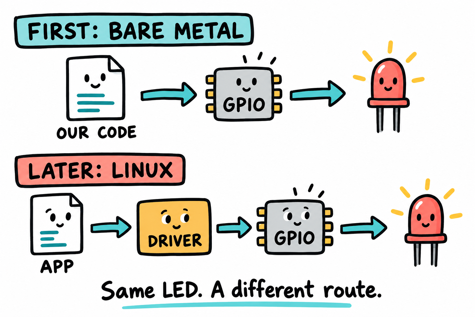
We will visit this LED twice. First, our small program does the register work. Later, a Linux application uses a driver interface. The two rows are different experiments on the same hardware, not two programs trying to drive it at once.¶
There are optional routes into PREEMPT_RT, containers, and Part IX’s virtualization and mixed-core designs. These address different timing, isolation and deployment needs. Read them when that design question matters, not because every product needs every layer.
This is not a Linux application-programming book. We use a shell and small C test programs, but do not teach POSIX threads or select/epoll in depth. Kubernetes deployment and Android system builds are outside the route.
1.5 How each chapter is organized¶
Read the early chapters with a question in mind. Why does an application need a driver? Why does a boot image contain addresses before its code? Why are there several files called a kernel? Names and formats become useful when they answer a concrete question.
A chapter develops the mechanism, the choices it enables, and the constraints those choices introduce. Code, commands and diagrams make the interfaces visible. Key Notes collect the architectural points worth retaining: ownership, dependencies, tradeoffs and failure boundaries. Pitfalls explain where a plausible design or implementation can go wrong. There are no assigned labs or completion tests.
The references at the end are for a second pass. You do not need to read every linked manual or source file before continuing. Use them when you want a fuller explanation or need to settle a specific question.
1.6 Key Notes¶
Layers have owners. ROM, bootloader, kernel and application make different decisions. A failure becomes easier to reason about when the responsible layer is identified.
Interfaces carry assumptions. Image headers, calling conventions, Device Tree properties and driver APIs are contracts between components, not arbitrary syntax.
Design choices have costs. A simpler boot path, a richer filesystem or stronger isolation changes memory, recovery, maintenance and integration requirements.
Code is evidence of an intended mechanism, not of its outcome. Compilation, simulation and physical measurement answer different questions.
Implementation assistance does not remove engineering judgment. Generated code still has to fit the chosen ownership, timing, resource and failure model.
Hardware limits remain real. Electrical compatibility, storage identity and irreversible operations require specific evidence regardless of how the code was produced.
1.7 Code listings¶
Code is included in the chapters to expose a mechanism or interface. A startup file can look uninviting at first. Read it in the groups explained beside it: prepare the stack, clear a memory range, call the C function. The valuable question is why each operation belongs there and what depends on its order, not whether you can type every line.
Pseudocode shows an idea, a fragment shows part of a larger implementation, and illustrative output shows what a tool may report. Some longer examples show how the pieces fit. None replaces board qualification or a complete product design. A retained command sequence is an explanatory example, not a reading assignment.
1.8 Conventions¶
Prompts¶
Once the board runs software, you will often have two terminals open: one on the host and one connected to the board. The prompt tells you where a command belongs:
$        a regular user prompt on the host PC
#        a root prompt on the host PC (used sparingly)
=>       the U-Boot prompt
target$  a regular user prompt on the i.MX6ULL board
target#  a root prompt on the i.MX6ULL board
Type the command after the prompt, not the prompt itself. For example, $ sudo picocom ... means enter sudo picocom ... in your normal host terminal. The # in a root-prompt example is different from the # that begins a comment inside a shell script. Blocks without prompts are file contents or command blocks identified in the surrounding text.
Registers and bits¶
Registers are written in uppercase with the bank prefix from the reference manual:
CCM_CCGR5 |= (3u << 24); /* UART1 CG12: bits 25:24 = 11 */
This is register pseudocode, not a complete UART setup. UART1’s two-bit gate is in CCM_CCGR5 at 0x020C407C; 11 enables it in run and WAIT modes, but not STOP [RM 18.6.28]. MMIO definitions, pin mux, and the UART root clock are supplied later.
When a bit field is named, square brackets denote a field rather than C array syntax:
CCM_CCGR5[CG12] = 3; /* the same gate field, notation only */
Numeric notation¶
Hex values are written with the C 0x prefix everywhere except inside hex dumps. Megabytes and gigabytes use the IEC binary prefixes (MiB, GiB) when precision matters. “MB” is shorthand for the marketed quantity (board has “512 MB DDR3”, the chip is actually 512 MiB).
Addresses¶
When we cite a memory address, we cite the physical address unless we are discussing MMU mappings. Physical addresses on i.MX6ULL are 32 bits. In Chapter 17, virtual addresses are shown in the kernel and user ranges being discussed.
Citations¶
References to the i.MX6ULL Reference Manual are written as [RM §28.5.3]. This means Chapter 28, Section 5.3 of the i.MX 6ULL Applications Processor Reference Manual, revision 1, 11/2017. Linux source citations look like [linux: drivers/gpio/gpio-mxc.c:142] and refer to v6.6 unless noted.
Diagrams¶
The small concept sketches pause over one idea at a time. Their captions explain the important distinction in ordinary text, too. A smiling chip is a character in the explanation, not an extra component to find on your board; these drawings are not wiring instructions or to-scale memory maps.
Detailed reference diagrams are also drawn with text, so they remain readable in the Markdown source as well as on the website. The sketches are ordinary image files; you do not need a separate diagram-rendering tool to read or build the book.
1.9 How the chapters depend on each other¶
On a first reading, Chapters 1-8 establish the host/target distinction, the core, and the boot-image contract. Part II uses a small LED/UART program to expose startup, clocks, interrupts and memory ownership. Part III shows how U-Boot organizes those responsibilities. The kernel, root filesystem and driver parts then explain the next layers. Understanding an earlier mechanism helps with a later one, but completing a program is not a condition for continuing.
Readers interested primarily in the boot stack can move from the foundations to Chapter 19’s U-Boot source study, then return to Part II when a register-level detail needs explanation. Physical use of those examples has separate board prerequisites; reading the architecture does not require a connected board.
The table below suggests routes by the design question you want to answer:
If you… |
Read |
Skim |
Skip |
|---|---|---|---|
Want the full architectural progression |
Numbered core chapters |
supplementary detail as needed |
unrelated optional designs |
Have MCU experience but are new to Linux |
1-17, 19-24, kernel/rootfs and driver foundations |
familiar C/build detail |
unrelated peripheral add-ons |
Want the Linux boot architecture first |
1-8, 19-30, 31-35 |
9-17 |
optional peripheral implementations |
Already shipped Linux on a different SoC, want i.MX6ULL specifics |
1, 5, 7, 19-24, 27 |
25-35 |
9-18 |
Maintain an existing BSP, want driver depth |
1, 27, 36+ |
25-35 |
2-24 |
When starting in the middle, use the chapter’s opening and Key Notes to identify its assumptions. Knowing a similar mechanism on another chip does not supply that board’s wiring, timing or memory configuration.
1.10 A note on the i.MX 6ULL Reference Manual¶
Keep revision 1 (11/2017) of the i.MX 6ULL Applications Processor Reference Manual nearby. At 4,127 pages, it is a poor place to start with “I should learn all of this.” Start with “I need the clock gate for UART1.” That question takes you to a few relevant pages and gives you a reason to read them carefully.
For a new peripheral, start with these five questions:
Where are its registers? Start with the system memory map.
Which clock reaches the block? Follow the CCM clock path and gate.
Which pads carry its signals? Check the IOMUXC tables against the schematic.
Which interrupt ID identifies it? Look in the GIC SPI table if the block generates interrupts.
In what order should it be initialized? Look for the manufacturer’s sequence near the start of the block’s chapter.
The answers connect the software interface to the schematic. Chapter 5 works through this search for UART1, and later peripheral chapters use it in context. The goal is not to finish the whole manual. It is to find the evidence that explains a particular design.
Before following the boot sequence, there is one change to the MCU picture worth understanding. You know how to write a GPIO register. Why would Linux put a driver interface between your application and that perfectly ordinary operation? That is where we begin.
Next: Chapter 2: What embedded Linux is. The full table of contents and draft status are reference pages, not prerequisites before Chapter 1.