Chapter 18A: Project organization
You want to add a button, but opening main.c also brings up clock setup,
UART registers, and the interrupt handler. Which parts belong to the new
feature, and which must remain untouched? A project layout should make that
decision easier without changing what the board does.
The example layout puts drivers into a small board support package (BSP) and gives their register definitions one home. This is the same separation you may have used with an MCU HAL: application code calls a driver; the driver knows the controller and the board wiring. No Linux service or device tree is involved in these bare-metal programs.
This chapter examines a refactor of the Chapters 10-17 design, not a new standalone firmware download or a required migration. Startup, linker layout and boot-image wrapper form a contract that remains intact when the C code moves. The following header is a useful subset, not every register needed by those earlier chapters.
18A.1 The problem we are solving
A project using the Chapter 16 or 17 mechanisms may have:
main.c:main()plus inline UART init, GPIO init, CCM writesstartup.S,link.ld, unchangedA growing list of
#define UART_UCR1 0x02020080and friends, scattered across filesFunction names like
uart_init,gpio_init,epit_init, whose declarations need a consistent home.
Two specific kinds of pain start to appear:
Duplicated hardware facts.
uart.cdefinesUART_UCR1;main.cindependently defines it with a typo. Separate C files are separate translation units, so both can compile and use different addresses. In a single translation unit, an incompatible macro redefinition normally produces a diagnostic. Neither situation is a reason to maintain two copies.Reuse friction. To use the Chapter 18 I²C driver in a new project, you copy
i2c.c, plus the relevant#defines frommain.c, plus the CCM gate bit, plus the IOMUX writes. That can mean five files per peripheral.
Separate the SoC register map (imx6ull.h) from driver behavior
(one folder per peripheral). Keep board choices, such as which pad drives
KEY0, named separately from generic GPIO offsets. In this small project they
can be a clearly marked board section of the same header. A new board then
changes those choices rather than pretending that all i.MX6ULL boards are wired alike.
18A.2 Target layout
bare-metal/
├── Makefile                     # top-level build
├── link.ld                      # unchanged
├── startup.S                    # unchanged
├── imx6ull.h                    # shared register definitions subset
├── main.c                       # only application logic
└── bsp/
    ├── clk/
    │   ├── bsp_clk.h
    │   └── bsp_clk.c            # was clocks.c
    ├── gpio/
    │   ├── bsp_gpio.h
    │   └── bsp_gpio.c
    ├── uart/
    │   ├── bsp_uart.h
    │   └── bsp_uart.c
    ├── int/                     # interrupts / GIC
    │   ├── bsp_int.h
    │   ├── bsp_int.c
    │   └── irq_entry.S          # the IRQ entry asm from Ch 15
    ├── gpt/
    │   ├── bsp_gpt.h
    │   └── bsp_gpt.c
    ├── epit/
    │   ├── bsp_epit.h
    │   └── bsp_epit.c
    └── delay/
        ├── bsp_delay.h
        └── bsp_delay.c
Conventions:
bsp_<peripheral>.hhas only public-facing declarations: the API functions, and the enum types the API uses. No raw register addresses.bsp_<peripheral>.chas the function bodies. Includesimx6ull.hfor register addresses.imx6ull.his the only place that names registers. Every other file uses those names.
Include each driver’s own header in its implementation too. That lets the compiler compare the public declaration with the definition. A driver may also include another driver’s public header when it actually uses that API; for example, a buzzer driver may depend on the delay driver.
18A.3 Writing imx6ull.h
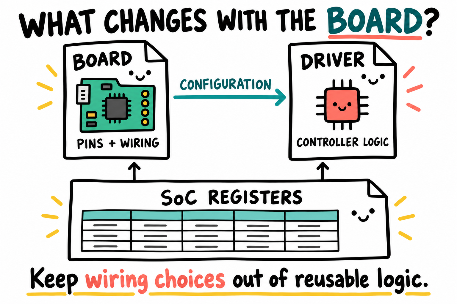
The register map describes the SoC. The board chooses how its signals are wired. Keep those choices visible when moving code into a driver, even if this small project stores both sets of definitions in one header.
The file is long but mechanical. Section it by peripheral block:
#ifndef IMX6ULL_H
#define IMX6ULL_H

#include <stdint.h>
#define REG(addr) (*(volatile uint32_t *)(uintptr_t)(addr))

/* ============================================================
 * CCM — Clock Controller Module (RM ch. 18)
 * Base: 0x020C4000
 * ============================================================ */
#define CCM_BASE        0x020C4000U
#define CCM_CCR         (CCM_BASE + 0x00)
#define CCM_CACRR       (CCM_BASE + 0x10)
#define CCM_CBCDR       (CCM_BASE + 0x14)
#define CCM_CBCMR       (CCM_BASE + 0x18)
#define CCM_CSCMR1      (CCM_BASE + 0x1C)
#define CCM_CSCDR1      (CCM_BASE + 0x24)
#define CCM_CCGR0       (CCM_BASE + 0x68)
#define CCM_CCGR1       (CCM_BASE + 0x6C)
#define CCM_CCGR2       (CCM_BASE + 0x70)
#define CCM_CCGR3       (CCM_BASE + 0x74)
#define CCM_CCGR4       (CCM_BASE + 0x78)
#define CCM_CCGR5       (CCM_BASE + 0x7C)
#define CCM_CCGR6       (CCM_BASE + 0x80)
#define CCM_CDHIPR      (CCM_BASE + 0x48)

/* CCGR per-peripheral gates -- 2 bits each, 16 gates per CCGRx register */
#define CCGR_GPIO1_GATE   (3u << 26)   /* CCGR1[27:26] */
#define CCGR_GPIO5_GATE   (3u << 30)   /* CCGR1[31:30], see note below */
#define CCGR_GPT1_GATE    (15u << 20)  /* CCGR1[23:20]: serial AND bus */
#define CCGR_EPIT1_GATE   (3u << 12)   /* CCGR1[13:12] */
#define CCGR_UART1_GATE   (3u << 24)   /* CCGR5[25:24] */
#define CCGR_I2C1_GATE    (3u << 6)    /* CCGR2[7:6]   */

/* ============================================================
 * CCM analog PLLs and PFDs (RM ch. 18)
 * Base: 0x020C8000
 * ============================================================ */
#define ANATOP_BASE     0x020C8000U
#define ANATOP_PLL_ARM  (ANATOP_BASE + 0x000)
#define ANATOP_PLL_SYS  (ANATOP_BASE + 0x030)
#define ANATOP_PFD_528  (ANATOP_BASE + 0x100)
#define ANATOP_PFD_480  (ANATOP_BASE + 0x0F0)

/* ============================================================
 * GPIO1..GPIO5 (RM ch. 28)
 * ============================================================ */
#define GPIO1_BASE      0x0209C000U
#define GPIO2_BASE      0x020A0000U
#define GPIO3_BASE      0x020A4000U
#define GPIO4_BASE      0x020A8000U
#define GPIO5_BASE      0x020AC000U

/* Per-bank register offsets */
#define GPIO_DR_OFS     0x000
#define GPIO_GDIR_OFS   0x004
#define GPIO_PSR_OFS    0x008
#define GPIO_ICR1_OFS   0x00C
#define GPIO_ICR2_OFS   0x010
#define GPIO_IMR_OFS    0x014
#define GPIO_ISR_OFS    0x018
#define GPIO_EDGE_OFS   0x01C

/* Helper for indexed access */
#define GPIO_DR(bank)   REG((bank) + GPIO_DR_OFS)
#define GPIO_GDIR(bank) REG((bank) + GPIO_GDIR_OFS)
#define GPIO_PSR(bank)  REG((bank) + GPIO_PSR_OFS)

/* ============================================================
 * UART1 and UART2 subset (RM ch. 55)
 * ============================================================ */
#define UART1_BASE      0x02020000U
#define UART2_BASE      0x021E8000U
#define UART_URXD_OFS   0x000
#define UART_UTXD_OFS   0x040
#define UART_UCR1_OFS   0x080
#define UART_UCR2_OFS   0x084
#define UART_UCR3_OFS   0x088
#define UART_UCR4_OFS   0x08C
#define UART_UFCR_OFS   0x090
#define UART_USR1_OFS   0x094
#define UART_USR2_OFS   0x098
#define UART_UBIR_OFS   0x0A4
#define UART_UBMR_OFS   0x0A8
#define UART_UTS_OFS    0x0B4

/* ============================================================
 * GPT1, EPIT1, EPIT2 (RM ch. 30, 24)
 * ============================================================ */
#define GPT1_BASE       0x02098000U
#define EPIT1_BASE      0x020D0000U
#define EPIT2_BASE      0x020D4000U

/* ============================================================
 * IOMUXC (RM ch. 32)
 * ============================================================ */
#define IOMUXC_BASE     0x020E0000U
/* Pad mux + pad ctl offsets vary per pad; use the pad-specific addresses
 * directly, looked up from the RM IOMUX tables. */

/* ============================================================
 * GIC v2 (Cortex-A7 internal at 0x00A01000 / 0x00A02000)
 * ============================================================ */
#define GICD_BASE       0x00A01000U
#define GICC_BASE       0x00A02000U

#endif /* IMX6ULL_H */
Bring across the remaining definitions used by your existing drivers; do not
delete one merely because it is absent from this subset. REG expresses a
volatile MMIO access, not a memory barrier. If you retained Chapter 17’s MMU,
the peripheral ranges must still use appropriate Device memory attributes.
Two details deserve a source check. GPT1 has bus and serial gates, so the
combined mask covers both. The supplied IMX6ULLRM Rev. 1 calls CCGR1 CG15
reserved, whereas the Linux v6.12 i.MX6UL/ULL clock driver
defines GPIO5 at offset 0x6C, shift 30. The GPIO5 mask above follows that
implementation; it is not a literal transcription of the supplied RM table.
Gate value 11 enables a clock in RUN and WAIT, not STOP.
18A.4 A peripheral driver, refactored
In this layout, Chapter 13’s read-only clock audit belongs in
bsp/clk/bsp_clk.c, includes bsp_clk.h instead of clocks.h, and uses
register names consolidated in imx6ull.h. The following selective gate
helper shares that module. It does not replace the audit or introduce a
generic PLL transition routine:
#include "bsp_clk.h"
#include "imx6ull.h"

void clk_enable_lab_gates(void)
{
    REG(CCM_CCGR1) |= CCGR_GPIO1_GATE | CCGR_GPT1_GATE | CCGR_EPIT1_GATE;
    REG(CCM_CCGR5) |= CCGR_UART1_GATE;
}
The corresponding header:
#ifndef BSP_CLK_H
#define BSP_CLK_H
#include <stdint.h>

void clk_enable_lab_gates(void);
uint32_t clocks_get_arm_hz(void);
uint32_t clocks_get_ahb_hz(void);
uint32_t clocks_get_ipg_hz(void);
uint32_t clocks_get_uart_hz(void);
uint32_t clocks_get_mmdc_hz(void);

#endif
The audit function bodies still come from Chapter 13; a declaration alone
does not supply them. In particular, the timer initializer needs the actual
supported IPG rate, not an assumed 66 MHz value. The gate helper does not set
UART baud rate or GPT prescalers, and enabling a gate is not permission to
change a live clock root. Retain the approved ROM/board clock configuration
for these examples; do not call a leftover clk_init_main() or clocks_init()
that reprograms it without a board-qualified transition.
18A.5 The top-level Makefile
Use the Chapter 3 environment in a Linux terminal (including your
configured WSL shell), not PowerShell. Keep the official Arm 13.2.Rel1
arm-none-eabi toolchain in its existing project-local directory; do not
rename it, install a replacement system compiler, or edit .bashrc.
$ . ~/imx6ull/scripts/env.sh
$ command -v arm-none-eabi-gcc
$ arm-none-eabi-gcc --version
$ cd ~/imx6ull/src/bare-metal
Check that the path and version identify the selected no-OS compiler before
building. The directory above is the layout in Section 18A.2; substitute
your own project directory if you used a different name. Build as your
normal user. Save the following as Makefile, with literal tabs at the
start of recipe lines:
CROSS    ?= arm-none-eabi-
CC       := $(CROSS)gcc
OC       := $(CROSS)objcopy
SIZE     := $(CROSS)size

ARCHFLAGS := -mcpu=cortex-a7 -marm -mfloat-abi=soft -mgeneral-regs-only
CFLAGS    := $(ARCHFLAGS) -std=gnu11 -ffreestanding -fno-builtin \
             -fno-pie -fno-stack-protector -fno-common \
             -fno-unwind-tables -fno-asynchronous-unwind-tables \
             -O2 -g -Wall -Wextra -Werror=implicit-function-declaration
ASFLAGS   := $(ARCHFLAGS) -g
LDFLAGS   := $(ARCHFLAGS) -nostdlib -Wl,-T,link.ld,-Map,app.map
LDLIBS    := -lgcc

# One directory level of BSP sources; keep experiments outside this tree.
BSP_DIRS := $(patsubst %/,%,$(wildcard bsp/*/))
CPPFLAGS := -I. $(addprefix -I,$(BSP_DIRS))

BSP_C    := $(wildcard bsp/*/*.c)
BSP_S    := $(wildcard bsp/*/*.S)
TOP_C    := $(wildcard *.c)
TOP_S    := startup.S

OBJS     := $(BSP_C:.c=.o) $(BSP_S:.S=.o) $(TOP_C:.c=.o) $(TOP_S:.S=.o)

all: app.bin

%.o: %.c Makefile
	$(CC) $(CPPFLAGS) $(CFLAGS) -MMD -MP -c -o $@ $<

%.o: %.S Makefile
	$(CC) $(CPPFLAGS) $(ASFLAGS) -MMD -MP -c -o $@ $<

app.elf: $(OBJS) link.ld Makefile
	$(CC) $(LDFLAGS) -o $@ $(OBJS) $(LDLIBS)
	$(SIZE) $@

app.bin: app.elf Makefile
	$(OC) -O binary $< $@

clean:
	rm -f $(OBJS) $(OBJS:.o=.d) app.elf app.bin app.map

-include $(OBJS:.o=.d)

.PHONY: all clean
With unchanged inputs and outputs present, a second make invocation should
not compile or link anything. app.bin is still only the payload. Any board
transfer requires the matching ROM wrapper and its placement/size checks.
What the rules now account for:
Source discovery and includes agree. Both cover
bsp/<driver>/, one level deep. A newbsp/key/directory supplies both sources and an include path. Do not leave two alternative implementations or twomainfunctions inside the discovered tree; avoid a.cand.Swith the same basename, since both would map to one.o.Header changes rebuild their users. GCC’s
-MMD -MPcreates one.ddependency file per object;-includereads it after the default target. A driver includes its own header and the headers of APIs it calls. Include-path visibility does not enforce architectural layering. GNU make’s prerequisite guidance explains why header dependencies are needed.Edited build flags are inputs too. Objects and outputs depend on
Makefile. Command-line overrides and a changed compiler executable/path are not automatically tracked: usemake cleanbefore rebuilding with those changes. Removing or renaming a discovered source also warrants a clean rebuild, since an old ELF does not record the previous source list for Make.The integer-only contract is explicit. ARM state, soft-float ABI, and
-mgeneral-regs-onlykeep these C drivers out of VFP/NEON registers. Apply that policy to all C objects, including interrupt handlers; do not mix in hard-float objects. The same architecture flags reach the link step.-nostdlibremoves automatic runtime libraries, so-lgccfollows the objects for compiler-generated helpers. It does not supplyprintf,memcpy, or a C startup.
The linker and startup remain part of the refactor’s contract:
For the fresh-ROM OCRAM route, place
.vectorsfirst at0x00908000, useENTRY(_vectors), and make its first instruction branch to_start. Set the wrapper’s entry to that same vector address. Install VBAR with the required alignment and synchronization; keep the exception-base selection consistent with it.Keep
.dataand.bssends padded to four bytes for the word-copy/word-clear loops. Reserve the Chapter 10 4 KiB stack explicitly and retain its overlap assertions. If IRQ support is included, retain its separately allocated mode stack and 8-byte C-call alignment too.Keep the complete ROM-loaded image, including wrapper overhead, within the chosen limit ending at or below
0x00918000. Linker assertions for payload RAM alone do not check wrapper bytes; rerun the Chapter 11 image-size checks.Expect a fresh-ROM handoff, not a jump out of an arbitrary running Linux/U-Boot image. Do not assume that all caches are off. Preserve the startup’s documented handoff preparation and, when retaining the MMU example, the peripheral memory attributes and cache/table maintenance. Moving a source file does not repair a handoff protocol.
If that maintenance uses set/way operations across L1 and L2, retain the DSB between cache levels required by supplied chip erratum ERR008958. An organized source tree does not remove silicon-specific sequencing.
18A.6 Cost of the refactor
You gain more files and more explicit dependencies. In return, a UART change
has a predictable location, and an application can include bsp_uart.h
without copying its register map. The tradeoff is clearer ownership at the
cost of more files. There is no fixed line-count or time saving to promise.
A public-header change illustrates the build contract: every affected
implementation must rebuild. Without that dependency, an organized layout
still permits stale code. The .d files therefore belong to the refactor
itself, not to a later cleanup.
18A.8 Key Notes
SoC offsets, board wiring and driver behavior describe different ownership domains. A shared hardware header prevents duplicate definitions without making every board’s routes interchangeable.
Public headers define driver interfaces and are included by their own implementations. Include-path visibility makes names available but does not enforce dependency direction or prevent architectural cycles.
Moving files does not replace startup, vector placement, stack budgets, image wrapping or cache-handoff requirements. Those contracts survive the refactor unchanged.
Source discovery and object naming constrain the build. Two alternative implementations in the discovered tree, or a C and assembly source mapping to the same object name, create ambiguity rather than modularity.
Header dependency files and Makefile prerequisites keep outputs tied to inputs. Compiler-path changes, command-line flag overrides and removed sources need separate clean-rebuild handling because these rules do not track them automatically.
Raw macros and verified SDK structs can express equivalent register accesses. Correct offsets, access types and semantics matter more than identical ELF bytes, which can change with link order and alignment.
The integer-only ABI and explicit libgcc link are system-wide contracts, including ISR callees. A gate helper supplies neither clock-root transitions nor a C runtime.
18A.9 Pitfalls
Confusing folder names with layering.
lib/,drv/, andbsp/are valid conventions. Herebsp/names our board support code; consistent ownership and includes matter more than the spelling.Including drivers from
imx6ull.h. It reverses the intended dependency direction and can create include cycles. Keep the hardware description independent of driver APIs.Assuming
static inlinealways bloats code. A small accessor can be appropriate; unused inline functions need not be emitted. Keep substantial driver behavior in.cso it has one implementation and a clear API.Forgetting
-Ifor every BSP folder. Symptom:bsp_clk.h: No such file or directory. The$(addprefix -I,$(BSP_DIRS))line saves you.Conflicting definitions during SDK migration. The styles can coexist behind clear module boundaries, but duplicate base names and incompatible register types cannot. Convert one implementation deliberately; it is not a blind global replacement.
Duplicate vectors or IRQ entries. Moving
irq_entry.Smust remove its old definition, not add another. Keep vector ordering, VBAR setup, and mode-stack allocation in the linked result.
18A.10 Going deeper
Linux kernel
arch/arm/include/asm/io.handarch/arm/include/asm/hardware/, the kernel uses the same “one header per controller” pattern at scale.U-Boot
arch/arm/include/asm/arch-mx6/imx-regs.h, register addresses for i.MX6 family in U-Boot.A verified NXP i.MX6ULL SDK package: inspect its
MCIMX6Y2.h, supporting headers, release notes, and license before adopting the struct-based map.GNU make manual, automatic prerequisites: the header-rebuild mechanism used above. Check GCC’s
-MMDand-MPdescriptions alongside it.
Next chapter: Chapter 18B: Button input and beep. The layout separates a board-specific input/output path from event filtering and timing policy.