Chapter 24G: Factory and recovery modes in U-Boot
The serial prompt still works, but the kernel file is gone. You do not need a complete Linux system to repair that failure. U-Boot already has a storage driver and, with the right USB controller support, can offer a service port to a host computer.
The service port is also a new way to damage the board. A host that sees a
writable disk can overwrite the accepted slot, credentials, or boot metadata.
We will distinguish recovery levels first, then restrict what the host can
reach. Begin with Chapter 19’s MINI vendor baseline and UART1 console.
The UMS/DFU configurations and board code below target upstream U-Boot
v2026.04, in the separate mx6ull_pa_mini migration, not the older vendor
tree. Keep the baseline boot/recovery route available while adding service.
The MINI already has the necessary connector routes; it does not need a
generic EVK carrier. Chapter 22 now supplies a complete modern MINI source
candidate for UART/storage and source-checked ENET2 support, with physical
operation still unqualified. It deliberately omits USB, so integrate the
device-mode path here and plan a writable service target explicitly.
Its ENV_IS_NOWHERE environment is nonpersistent; that fact is separate
from USB support or the safety of exposing media.
Chapter 19’s initial vendor example also disables CMD_USB. The USB_TTL serial
bridge does not need that command; UMS/DFU below are later feature builds,
not services promised by that initial UART/storage binary.
24G.1 Recovery levels
Level |
Code that must already work |
Boundary |
|---|---|---|
Boot ROM SDP |
i.MX6ULL ROM and its selected USB boot path |
Can load a suitable image without working U-Boot on storage; host procedure determines whether anything is written |
U-Boot USB recovery |
U-Boot, DDR, USB, and storage drivers |
Repairs selected later-stage contents, not a bootloader that cannot start |
Linux recovery image |
A separate bootable Linux image |
Richer diagnostics/networking, with more dependencies |
Main Linux |
Normal kernel and rootfs |
Normal operation and controlled updates |
SDP is not UMS or DFU. ROM mode is selected by the board’s documented
boot-mode procedure. UMS and DFU are commands run by an already working
U-Boot. NXP’s uuu can orchestrate multiple stages/protocols; its presence
on the host does not identify which stage the target is running. Keep
Chapter 8’s exact ROM access procedure documented independently.
On MINI V2.2, the similarly shaped USB sockets have different jobs (supplied baseboard schematic, sheet 4; guide Sections 5.4.3, 5.4.10-11):
Board connector |
Actual route |
Use here |
|---|---|---|
|
CH340C USB-to-UART bridge, then UART1 |
Serial console; not ROM SDP, UMS or DFU |
|
i.MX6ULL USB_OTG1 D+/D-, ID/VBUS circuitry |
ROM USB boot and the intended U-Boot peripheral service connection |
|
USB_OTG2, with board 5 V on VBUS |
Host peripherals; not the host-PC service cable |
Use a data-capable host-to-USB_OTG cable and keep the independent USB_TTL serial console. Apply Chapter 8’s reviewed supply arrangement; connecting several powered cables is not a substitute for tracing the VBUS paths. ROM entry uses the MINI’s BOOT_CFG1 switch bank and USB setting from its own sheet-1 table/silkscreen, not the recovery key or EVK switch positions. KEY0 service entry only works after U-Boot reaches the key hook.
The modern image path uses ROM DCD initialization and u-boot-dtb.imx, with
no SPL. Preserve the MINI-matched DDR setup established during migration.
Do not copy an spl DFU target, raw offsets, or the EVK DCD from another
board into the MINI repair procedure.
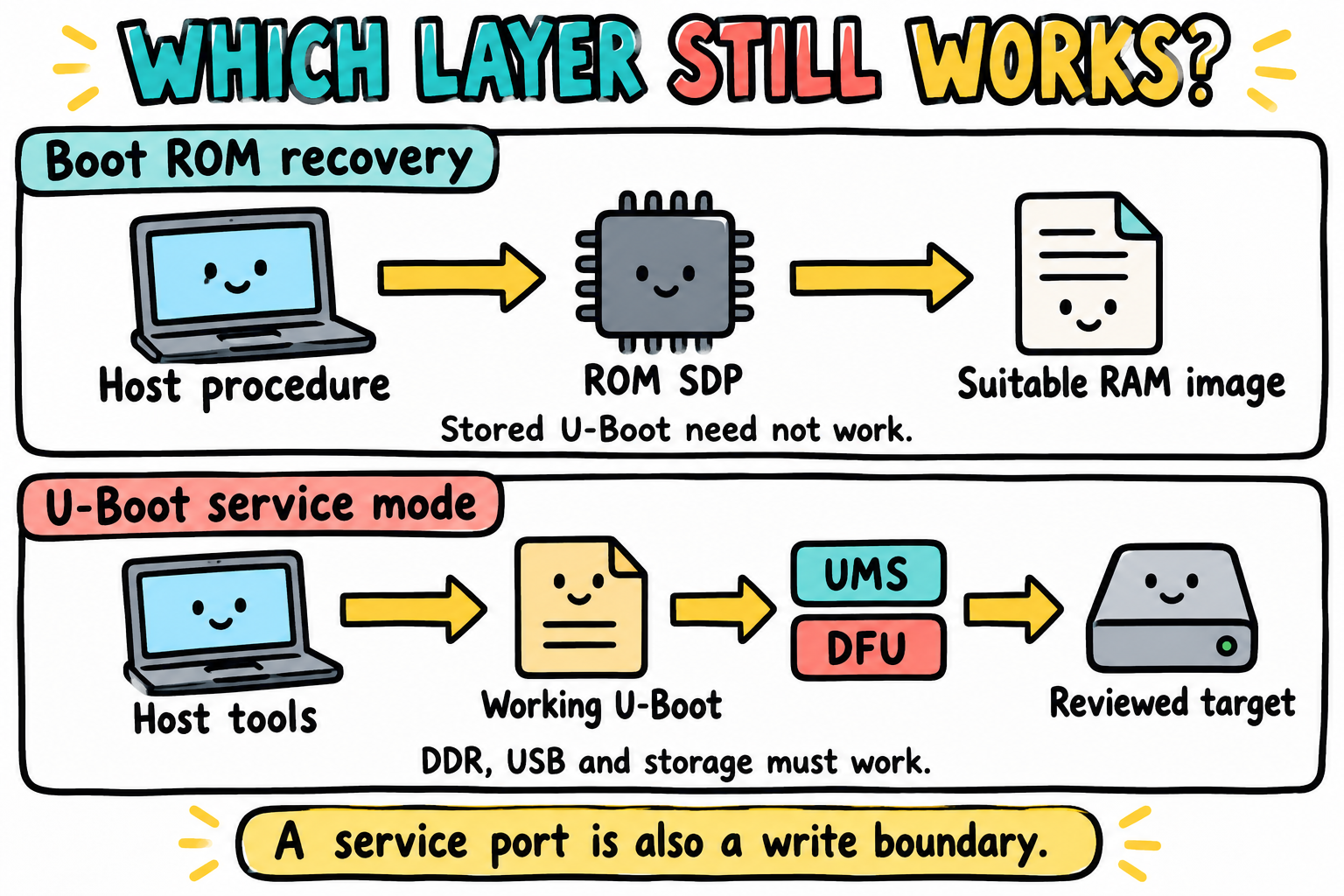
Recovery begins at the layer that still works. ROM SDP and U-Boot’s UMS or DFU are different protocols with different prerequisites. The host procedure and exposed target determine which writes are possible.
24G.2 Files changed in this chapter
File |
Responsibility |
|---|---|
|
USB device controller, UMS/DFU, GPIO commands |
|
USB role/PHY/power and recovery GPIO/pinctrl |
|
Read the key and override both automatic boot paths |
|
Reviewed recovery command defaults |
These are modern-port files, not vendor target filenames. Merge into the
existing port. A second board_late_init() is a duplicate
symbol, not an additional callback. Compiled defaults also do not overwrite
an existing saved environment.
24G.3 Choose the recovery method
Method |
Host view |
Main risk |
|---|---|---|
UMS |
A block device, either whole medium or selected partition |
Unrestricted writes within the exposed range; host automount |
DFU |
Named alternates through |
Names do not authenticate images or make writes atomic |
Fastboot |
Fastboot protocol and board-specific targets |
Layout and commands are a separate reviewed implementation |
TFTP |
Files fetched over Ethernet |
Network trust and verification; not a USB service |
Start with enumeration and inspection on a spare medium. Prefer a bounded partition over a whole disk. DFU becomes useful when factory tools need a specific target, but an accepted image must remain outside that target. Neither protocol is a production update policy by itself.
For MINI, choose USB plus local TF/eMMC access before relying on network
recovery. There is one RJ45 on ENET2, with PHY address 1. The guide
(pp. 274-275) identifies LAN8720 before V2.2 and SR8201F on V2.2 and later;
the supplied V2.2 sheet 3 shows SR8201F. The public vendor eMMC header
enables CONFIG_PHY_SMSC, which is not evidence of correct SR8201F support.
Do not promise working TFTP on V2.2. A modern network path requires the
actual PHY ID, reset and RMII clock behavior to be confirmed on the board.
Chapter 22 has completed the datasheet/source ID comparison: SR8201F-VB
ID words 0x001c/0xc816 give 0x001cc816, matching v2026.04’s RTL8201F
UID/mask entry. This makes PHY_REALTEK a concrete driver candidate, not
an observed MDIO ID or a bench-compatible link. Similar naming alone would
not establish this match. The comparison uses the CoreChips datasheet,
Tables 13-14
and the pinned driver entry.
Chapter 19’s initial vendor example disables networking
before the legacy network conditionals; it does not run an unreviewed PHY
hook or require Ethernet for the first UART/storage example.
24G.4 Enable USB recovery configs
For the MINI USB_OTG1 ChipIdea path in v2026.04, review this fragment with the migrated controller/PHY setup. A vendor USB implementation is a wiring and behavior reference, not a drop-in implementation of these modern APIs:
CONFIG_USB=y
CONFIG_DM_USB=y
CONFIG_USB_EHCI_HCD=y
CONFIG_USB_EHCI_MX6=y
CONFIG_USB_GADGET=y
# CONFIG_DM_USB_GADGET is not set
CONFIG_CI_UDC=y
CONFIG_USB_GADGET_DOWNLOAD=y
CONFIG_CMD_USB_MASS_STORAGE=y
CONFIG_DFU=y
CONFIG_DFU_OVER_USB=y
CONFIG_DFU_MMC=y
CONFIG_CMD_DFU=y
CONFIG_DM_GPIO=y
CONFIG_CMD_GPIO=y
CONFIG_CMD_GPIO_READ=y
CONFIG_BOARD_LATE_INIT=y
CI_UDC is the device-controller implementation. In this release it depends
on !DM_USB_GADGET; that is distinct from DM_USB. The ChipIdea gadget path
uses i.MX EHCI setup through usb_setup_ehci_gadget(). Generic USB/gadget
options alone are insufficient. Check the generated .config and the
controller implementation.
Select USB_OTG1 for the service connection, with the intended peripheral
role; inspect its DT dr_mode, PHY, VBUS handling, and any board hooks.
Sheet 4 shows the OTG port’s MT9700 supply switch and VBUS/ID circuitry;
do not invent a spare GPIO-based VBUS enable or treat USB_OTG2 as the gadget.
Do not drive host VBUS while connected as a device. Chapter 8’s power
and back-power checks apply to USB and the serial adapter too.
Set USB_GADGET_MANUFACTURER, USB_GADGET_VENDOR_NUM, and
USB_GADGET_PRODUCT_NUM to identities authorized for your board/workflow.
No borrowed ROM VID/PID is assigned here: ROM enumeration and a U-Boot gadget
are different devices. CMD_GPIO_READ is required for gpio read.
24G.5 Manual UMS test
UMS is writable. Linux being absent does not make it safe. Before starting, identify the target medium and selected partition, ensure no target command will also access it, and disable host automount through the host’s normal per-session controls. Use a dedicated lab host if that cannot be guaranteed.
Use the MINI’s identified spare TF card as the first service medium; the core’s eMMC is a separate target, and the MMC commands below do not expose NAND. Inventory the medium on the UART console first. Chapter 24F’s table proposes a layout, not one installed by the vendor baseline or Chapter 22. Before service, qualify every exposed byte range. If using A/B, pass 24F.3’s persistence/layout gate too. UMS itself does not require a persistent environment, but RAM-only environment support does not make storage exposure safe. On that qualified disposable layout, exposing B’s boot partition is bounded:
pa-mini=> mmc list
pa-mini=> mmc dev 0
pa-mini=> mmc info
pa-mini=> part list mmc 0
pa-mini=> ums 0 mmc 0:3
Do not run this until device 0 and partition 3 have been confirmed. The first
0 is the USB gadget controller argument. 0:3 is the MMC device/partition;
ums 0 mmc 0 instead exposes the whole medium, including raw boot and
environment ranges. See UMS syntax.
On the host, compare before/after inventories, without mounting or writing:
$ lsblk -o NAME,PATH,SIZE,MODEL,SERIAL,TRAN,TYPE,MOUNTPOINTS
A partition exposed as one LUN can appear as a whole host block device
containing a filesystem directly, not as /dev/sdX1. Disk letters and USB
transport alone are not identity proof. Do not provide a guessed path to
mount, a formatter, or an image writer.
For later authorized copying, use the exact identified LUN, only one host
filesystem owner, and the approved repair procedure. Before leaving UMS,
require successful writes and flushes, unmount/eject on the host, and confirm
no remaining mounts. If unmount fails, stop; do not force it. Then press
Ctrl-C in U-Boot. Never boot Linux, reset the target, or access its filesystem
from another U-Boot command while the host still owns it.
24G.6 Manual DFU test
Begin with a file target, not raw bootloader sectors. On the same separately qualified layout, assuming B’s boot partition is FAT:
pa-mini=> setenv dfu_alt_info 'splash.bmp fat 0 3'
pa-mini=> dfu 0 mmc 0 list
pa-mini=> dfu 0 mmc 0
Here splash.bmp is the actual target filename, not a label for an entire
partition. If the partition is ext4, the target grammar must use ext4
and the build needs the corresponding write support. FAT writes need
CONFIG_FAT_WRITE; enable it only for an approved write workflow.
On the host, list descriptors only:
$ dfu-util -l
Require the intended device identity and alternate name in actual output.
Enumeration is not a write/verification test. No dfu-util -D, raw offset,
or bootloader write recipe is supplied here. End the session with the
console’s Ctrl-C or the approved host detach procedure, after transfers are
complete. Do not assume it automatically resets or boots Linux.
DFU documentation describes
raw, part, fat, and ext4 forms. For MMC, raw offset/size are interpreted
as block ranges by the backend; they are not interchangeable with byte
addresses or .imx file offsets. Review drivers/dfu/dfu_mmc.c for the exact
medium. Named targets still allow damaging writes, and script targets
execute downloaded commands. Do not expose scripts, fuses, or secrets as a
beginner recovery target.
24G.7 Add recovery environment commands
After the bounded manual test, add defaults to the existing header:
#define PA_MINI_RECOVERY_ENV \
    "recovery_ums=if test \"${update_allowed}\" = \"1\"; then " \
        "ums 0 mmc 0:3; else echo Recovery writes not authorized; false; fi\0" \
    "dfu_alt_info=splash.bmp fat 0 3\0" \
    "recovery_dfu=if test \"${update_allowed}\" = \"1\"; then " \
        "dfu 0 mmc 0; else echo Recovery writes not authorized; false; fi\0" \
    "recovery_boot=echo Recovery service selected; " \
        "run recovery_ums; echo Recovery service ended; false\0"
These are disposable-layout defaults, not a dynamic inactive-slot selector. Their partitions must actually exist in the separately qualified medium; they are not allocations supplied by Chapter 22. They expose partition 3 even if B later becomes accepted. Before real deployment, derive the allowed target from trusted policy or use a separate service partition. Never present this fixed mapping as A/B-safe.
The deliberate false leaves the automatic path stopped after service
exit/failure. It must not fall through into a second normal/network boot.
To choose DFU in RAM, set recovery_boot to the same wrapper with
run recovery_dfu. Keep Chapter 24F’s normal and alternate commands; do not
add another compiled bootcmd definition here.
Both USB defaults are writable, so they require a fresh update_allowed=1
decision from Chapter 24H’s reviewed power policy, not merely permission to
boot. Keep its fail-closed default at zero, once in the combined environment.
For a supervised spare-medium lab without a monitor, an operator may set
that variable in RAM only, after the approved stable-supply checks;
this is an explicit lab authorization, not invented voltage telemetry.
An unset/zero flag refuses the service. A product must refresh permission
before service and handle power deterioration during it; the shell gate is
not authentication or a durable-write guarantee.
24G.8 Detect the recovery key in board code
On MINI V2.2, KEY0 connects through IMX1 B48 to UART1_CTS, muxed here
as GPIO1_IO18, GPIO1 bit 18, active-low. Sheet 2’s R12 supplies the
10 kOhm pull-up and the switch pulls the net to ground. This agrees with
the guide’s MINI Section 5.4.13. Trace the baseboard connection, not the
core sheet’s inherited KEY aliases: B49/GPIO1_IO01 instead carries
GBC_KEY/AP_INT, and is not this KEY0 switch.
Retain UART1_TXD/RXD for the USB_TTL console, but disable any competing
UART1 CTS hardware-flow-control ownership on this pad. KEY0 must remain an
input; do not use gpio set or gpio clear on it.
Add a board-owned property to the existing /chosen node:
/ {
    chosen {
        myorg,recovery-gpios = <&gpio1 18 GPIO_ACTIVE_LOW>;
    };
};

&iomuxc {
    pinctrl_recovery: recoverygrp {
        fsl,pins = <MX6UL_PAD_UART1_CTS_B__GPIO1_IO18 0x1b0b0>;
    };
};
Include the GPIO binding definitions and append &pinctrl_recovery to the
port’s existing IOMUXC default pinctrl hog. Do not replace its other groups.
The GPIO property does not apply pinmux by itself. The pad value is an
example to review with the board pull-up and electrical requirements.
The custom property is consumed by this board code, not a new upstream binding.
#include <dm.h>
#include <dm/ofnode.h>
#include <env.h>
#include <hang.h>
#include <stdio.h>
#include <asm/gpio.h>
#include <linux/delay.h>
#include <linux/errno.h>

static int pa_mini_recovery_key_pressed(void)
{
    struct gpio_desc key;
    ofnode node = ofnode_path("/chosen");
    int first, second, ret, free_ret;

    if (!ofnode_valid(node))
        return -ENOENT;
    ret = gpio_request_by_name_nodev(node, "myorg,recovery-gpios", 0,
                                    &key, GPIOD_IS_IN);
    if (ret)
        return ret;
    first = dm_gpio_get_value(&key);
    mdelay(20); /* Two separated samples; not a qualified debounce filter. */
    second = dm_gpio_get_value(&key);
    free_ret = dm_gpio_free(NULL, &key);
    if (first < 0)
        return first;
    if (second < 0)
        return second;
    if (free_ret)
        return free_ret;
    return first == 1 && second == 1;
}

static void pa_mini_apply_recovery_policy(void)
{
    int pressed = pa_mini_recovery_key_pressed();
    const char *command;

    if (!pressed)
        return;
    if (pressed < 0) {
        printf("Recovery key read failed: %d\n", pressed);
        command = "echo Key state unknown; false";
    } else {
        command = "run recovery_boot";
    }
    if (env_set("upgrade_available", "0") ||
        env_set("bootcmd", command) || env_set("altbootcmd", command))
        hang();
}
dm_gpio_get_value() applies GPIO_ACTIVE_LOW: a pressed physical low becomes
logical 1. The error path blocks automatic boot instead of interpreting
an I/O error as a released key. Call this helper from the existing
board_late_init() only after critical power policy allows service; do not
save its temporary overrides. Chapter 24F’s increment/limit selection occurs
later, so both commands must be overridden. In the nonpersistent modern candidate there
is no persistent candidate metadata to preserve, and reset reloads defaults.
Once 24F.3’s gate has selected persistent storage, with BOOTCOUNT_ENV the
temporary upgrade_available=0 is essential: it suppresses the later whole-environment
save, so these overrides are not persisted as part of a candidate attempt.
The stored candidate flag/count remain unchanged; a service-only entry does
not consume an attempt in this example. Do not invoke another saveenv in this
path without separately reconciling that state. Recovery still depends on usable
DDR and storage; it cannot repair a failure before this callback runs.
24G.9 Environment-only recovery key
For manual input inspection, v2026.04’s i.MX GPIO bank names use GPIO1_.
Confirm the actual name through gpio status -a, then read the physical level:
pa-mini=> setenv key_level
pa-mini=> gpio read key_level GPIO1_18
pa-mini=> printenv key_level
A pressed key should give 0 and a released key 1 here. Unlike a DT descriptor,
this command does not know the board’s active-low meaning. Check command
success and the value, not gpio input’s return status, which historically
returns the level and can confuse a high input with failure.
An environment script that changes bootcmd inside the already executing
bootcmd does not replace the remaining commands in that execution. For a
lab-only wrapper, directly branch to run recovery_boot or to the recorded
normal command. The alternate path must also branch through that check.
Use the C hook above for the integrated example; no fragile key script is
installed automatically.
24G.10 Factory test mode
Factory mode checks an identified assembly; recovery repairs storage. Do not turn an I2C address scan into a pass result: an ACK does not prove chip identity, and probing every address can have side effects. GPIO status does not establish continuity or safe output operation either.
A read-only MMC inventory can be gated honestly:
pa-mini=> setenv factory_mmc 'if mmc dev 0 && mmc rescan && mmc info; then echo TEST:MMC:ENUMERATED; else echo TEST:MMC:FAIL; false; fi'
pa-mini=> run factory_mmc
ENUMERATED is deliberately narrower than a destructive storage test. A
fixture’s PASS must correspond to a defined measurement, expected identity,
and limits. Keep command status as well as printed tokens. Never print
TEST:I2C:PASS merely because i2c probe ran.
A MINI factory policy separates UART1 console, identified TF/eMMC enumeration, KEY0 input, and the optional display’s observations. LED0 is GPIO1_IO03, active-low; BEEP is SNVS_TAMPER1/GPIO5 bit 1, active-low through sheet 2’s S8550 PNP high-side switch. Neither should be driven before reviewing its ownership/startup state. An I2C OLED or PMIC is not fitted on this baseboard, so do not require its ACK as a stock-board PASS. Ethernet remains a separate V2.2 PHY qualification, not an assumed fixture dependency. Keep serial output as the primary diagnostic channel.
24G.11 Recovery safety rules
Rule |
Why |
|---|---|
Deliberate physical entry and explicit serial message |
Avoid accidental service exposure |
Critical power veto before USB/storage service |
Repair writes also need reliable power |
Narrow, reviewed storage target |
Whole-disk UMS includes raw boot/environment data |
No simultaneous host/target ownership |
Filesystem caches are not coordinated |
Preserve an accepted image and metadata |
A service protocol is not rollback |
Define exit, disconnect, and watchdog behavior |
A timeout/reset during transfer can tear writes |
Document ROM SDP separately |
U-Boot cannot repair itself if it cannot run |
Restrict physical service access |
A button is not authentication; storage may contain secrets |
24G.12 Key Notes
ROM SDP, U-Boot USB service and Linux recovery require progressively more working software. A U-Boot gadget cannot repair an image that prevents U-Boot from starting.
USB_TTL is the UART bridge, USB_OTG is the intended peripheral-service route, and USB_HOST supplies host peripherals. Connector shape does not establish role or safe power routing.
UMS grants writable block access within its exposed range. One host or target filesystem owner is required, with completed flush/unmount before ownership returns to U-Boot.
DFU alternates describe target grammar and ranges, not authenticated or atomic updates. A file target narrows exposure, while raw block ranges and downloaded scripts enlarge it.
Fixed partition-3 service defaults are not a dynamic inactive-slot selector. Once B becomes accepted, that same mapping can expose the accepted image.
KEY0 dispatch overrides normal and alternate commands and suppresses the later bootcount save through a temporary candidate flag. Service exit deliberately does not fall through to boot.
Fresh write-power permission and restricted service access are separate requirements. Enumeration proves neither storage repair nor a factory PASS, and a physical button is not authentication.
24G.13 Pitfalls
Confusing ROM SDP with a U-Boot gadget. Identify who is executing.
Borrowed SPL offsets. This port has no SPL; raw layouts are board-specific.
Wrong KEY0 bit or polarity. Descriptor logical 1 means pressed; raw 0 does.
Assuming Linux absence makes UMS safe. Host writes can still destroy data.
Exiting with host caches dirty. Release the host LUN before target access.
Overriding only
bootcmd. An exceeded counter selectsaltbootcmdinstead.Treating enumeration as a production test. Match each PASS to real evidence.
24G.14 Going deeper
Supplied MINI V2.2 schematic, sheets 1-4, and the guide’s MINI Sections 5.4.3, 5.4.10-13, 5.4.15-19: connector roles, KEY0/BEEP routes, TF/Wi-Fi sharing and the V2.2 PHY change. Use the revision’s schematic when the guide’s copied prose disagrees.
DFU grammar and MMC backend.
NXP UUU sources/documentation: read the selected script’s protocols and writes before invoking it.