Chapter 24H: PMIC and power policy in U-Boot
The boot log stops when the storage device starts drawing current. Replacing the kernel will not fix a supply that collapses at that moment. Before calling it a software failure, ask which rail powers the device, what can observe that rail, and when the observation is possible.
On the supplied MINI V2.2 + core V2.0 design, power comes from discrete regulators, not an I2C PMIC. There is no fitted fuel gauge or external I2C rail monitor in these schematics. The useful stock-board example is to trace that real power tree and its reset/enable paths, then establish the stable supply arrangement for Chapter 19’s vendor baseline. A PMIC or monitor is an optional hardware extension, not something to discover by guessing an I2C address.
For that extension we use upstream U-Boot v2026.04 APIs in the separate
mx6ull_pa_mini migration. The policy can first be tested in host fixtures,
without changing real rails. It is not a drop-in patch for the older vendor
firmware, and the refusal stub below must not block an ordinary stock MINI.
Any hardware A/B integration still needs Section 24F.3’s persistence/layout
gate; stable power alone does not allocate environment or slot storage.
24H.1 What U-Boot should check
Condition |
Useful decision |
Earliest required protection |
|---|---|---|
Core or DDR supply outside specifications |
Do not attempt unsafe initialization |
Hardware/reset/ROM-time design, before using DDR |
Storage supply unavailable |
Do not load or write that device |
Before storage access, possibly before board late init |
Verified PMIC critical fault |
Refuse further automatic boot/service |
Before the affected load or operation |
Energy insufficient for an update |
Block writes while normal boot may remain possible |
Rechecked immediately before and during updating |
Optional LCD supply fault |
Leave LCD/backlight off, retain serial path if safe |
Before display initialization |
A PMIC status bit is not necessarily a measurement of a rail. An enable register describes a request, not proof that voltage has settled. An ADC reading also has accuracy, sample age, scaling, and operating limits.
The boot phase matters. The MINI image path is ROM + board-matched DCD +
full U-Boot, with DDR initialized before board_late_init(). A late check
cannot protect that first DDR access or diagnose every brownout: the CPU may already
have reset before it can print. It also cannot undo storage reads already
performed while loading the environment.
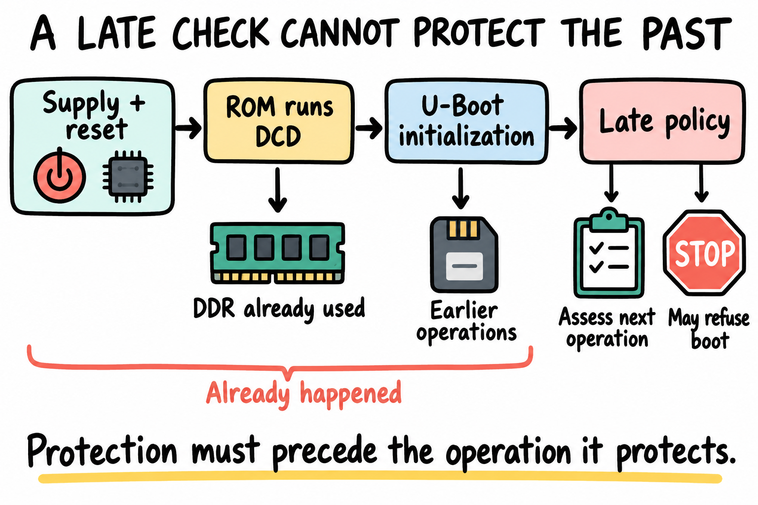
Put protection before the operation it protects. In this ROM+DCD path, a late power veto cannot protect the first DDR access or undo earlier device activity. The icons show phases, not fitted monitoring hardware.
24H.2 Three hardware patterns
Hardware |
What software can reasonably know |
|---|---|
Supported I2C PMIC |
Documented status/faults and regulator controls; only some chips expose voltage ADCs |
Fixed regulator with GPIO enable |
Intended enable state and, if wired, a separate power-good input |
ADC or battery gauge |
A documented conversion/energy estimate, not automatic authorization for every load |
Here is the actual starting point, from MINI sheet 4 and core sheets 1-2:
Fitted circuit |
Route/responsibility |
What it does not provide |
|---|---|---|
MINI U6, JW5060T |
DC input conversion to the 5 V supply path |
No I2C voltage/status registers |
MINI U4, JW5060T |
DCDC_5V to DCDC_3V3; EN receives |
No programmable PMIC merely because of the net name |
Core U8, TMI3211 |
Local DCDC_3V3; its |
Not an automatically readable GPIO/voltage sample |
Core U6/U11, MT3420B |
ARM/SoC and DDR supplies, respectively |
Not permission to adjust resistor-set rails from an I2C command |
Core U10, TMI809F and reset network |
Supply supervision/reset path |
No bootloader log guaranteed during a brownout |
MINI CR1, CR1220 backup cell |
VDD_COIN_3V to the core SNVS supply path |
Does not power Linux, storage or LCD; not an update-energy battery |
MINI U7, XC6206 |
USB-powered CH340C UART supply |
Serial enumeration does not prove the core rails are powered |
Trace DC_IN, K1, the two USB VBUS paths, the core supply inputs, and the approved probing points before choosing the Chapter 8 supply arrangement. The USB_TTL bridge has its own supply; SGM3157 switches isolate its UART lines when the board’s 3.3 V is absent. A live host serial device or lit power LED is therefore not a complete rail qualification.
For the stock MINI, finish that circuit audit and keep the established
vendor regulator/clock setup. Software has no documented input-voltage
telemetry here. Do not add pmic@2d or turn an enable net into an invented
“voltage OK” measurement. The vendor board source even contains PFUZE3000
code guarded for the 9x9 EVK; that inherited code is not fitted MINI
hardware.
For an optional monitored product, add a documented ADC/gauge/PMIC circuit with appropriate scaling, protection, address straps and fault wiring. P4 pin 43 is UART4_TXD/I2C1 SCL; pin 42 is UART4_RXD/I2C1 SDA. Pin 41 is ENET1_RXER, not SCL: these I2C signals are not a same-row header pair. MINI sheet 1 shows 4.7 kOhm pull-ups to DCDC_3V3. Check voltage compatibility, loading and UART4 ownership before using it. This gives a real bus starting point, not a specified monitor model or register map.
24H.3 Files changed in this chapter
File or area |
Responsibility |
|---|---|
|
Required I2C/GPIO/regulator support for real fitted devices |
|
Real compatible, bus, pinmux, rail and consumer relationships |
|
Measurement adapter and automatic-boot veto |
|
Fail-closed update and failure-message defaults |
Board design records |
Limits, timing, fault meanings, policy and test evidence |
These file names belong to the modern migration. The adapter in Section
24H.7 deliberately refuses operation until implemented. Keep it in a host
fixture or an explicit monitor-extension build; do not call it from the
stock MINI’s boot hook and label -ENOSYS a detected hardware fault.
24H.4 Enable useful configs
The following is the optional I2C monitor/regulator integration toolbox, not a requirement to enable PMIC support on the stock MINI. Select only what the actual design needs:
CONFIG_BOARD_LATE_INIT=y
CONFIG_DM_I2C=y
CONFIG_SYS_I2C_MXC=y
CONFIG_CMD_I2C=y
CONFIG_DM_GPIO=y
CONFIG_CMD_GPIO=y
CONFIG_DM_REGULATOR=y
CONFIG_DM_REGULATOR_FIXED=y
SYS_I2C_MXC is the i.MX I2C-controller symbol in v2026.04. It does not select
a PMIC chip driver. DM_REGULATOR supplies the regulator framework, and
DM_REGULATOR_FIXED supports fixed-regulator descriptions; neither creates
rails absent from the board. Enable the exact PMIC/regulator drivers after
checking their Kconfig dependencies and compatible matches.
CONFIG_CMD_POWEROFF is optional. It adds a command only when supported by
the configuration; a working platform poweroff implementation is still
required. Do not assume a command can remove board input power. A supported
poweroff must be qualified for rail ordering and watchdog behavior. We use
a serial-visible automatic-boot stop for the policy example instead.
Build using . ~/imx6ull/scripts/env.sh, ARCH=arm, and the selected
arm-none-linux-gnueabihf- compiler, with a separate O= directory as in
Chapter 24F. No .bashrc or host-global settings are needed.
24H.5 Example Device Tree for a PMIC
Device Tree is a hardware description, not a place to invent a register map. An added PMIC’s description depends on the fitted design and matching chip documentation. The table shows that evidence contract. On the stock discrete-power MINI, the correct result is no PMIC node:
Field |
Required evidence |
|---|---|
Bus and address |
Schematic nets, address straps, 7-bit address, verified controller sequence |
Compatible |
A match in the selected v2026.04 PMIC driver |
Register address width |
Driver/datasheet: one byte, two bytes, or another protocol |
Fault read |
Width, polarity, latching, read-to-clear/W1C side effects |
Voltage read |
Whether an ADC exists; byte order, coherent sample method, scale and units |
Regulators |
Real rail names, permissible ranges, enable polarity, consumers |
Timing |
Startup, settling, power-good, reset and shutdown order |
A fictitious myorg,teaching-pmic compatible has no upstream driver. A node
with such a name cannot make dm_i2c_reg_read() understand the chip.
Prefer the supported PMIC driver’s API and regulator bindings when available.
For a real GPIO-enabled rail, regulator-fixed uses the board’s actual
voltage, GPIO, polarity, and consumer phandle. Do not borrow GPIO4 bit 10 or
label an SD rail “eMMC” without evidence. Preserve existing fixed rails and
pinctrl in the modern tree. In particular, do not describe the core
PMIC_ON_REQ supply chain as an independently switchable display regulator.
regulator-always-on is a software constraint,
not proof of voltage; regulator-boot-on describes boot expectations, not a
measurement. Neither property grants permission to change a core/DDR rail.
24H.6 Manual PMIC read first
There is no stock MINI PMIC read to perform. Use this section only after installing the documented optional monitor/PMIC; otherwise continue with the stock circuit audit and the host policy example.
Begin with i2c bus and inspect the controller’s actual alias/sequence. The
schematic’s “I2C1” need not be U-Boot bus 1. Select only the identified bus.
A broad i2c probe sends bus transactions and is not guaranteed harmless for
every device, so prefer a reviewed read to a known fitted address.
The command shape below is not runnable until placeholders are resolved:
pa-mini=> i2c dev <verified U-Boot bus sequence>
pa-mini=> i2c md <verified 7-bit address> <safe status register>.1 <byte count>
.1 means a one-byte register offset; it is not the data width. A device with
a two-byte offset needs the corresponding .2 protocol, and some chips need
a driver-specific transfer instead. Do not read a latch-clearing register
merely to inspect it, and do not write an unknown bit to “clear the error”.
Record raw bytes and datasheet interpretation separately. No device address,
fault bit, voltage conversion, or successful read is supplied as a MINI fact.
24H.7 Example power policy code
There are two contracts. The adapter produces one validated snapshot using chip-specific rules. The policy decides whether that snapshot allows continued automatic boot or update. A communication error is not an ordinary voltage value.
This board-local example is compilable monitor-extension policy scaffolding, not a stock MINI PMIC driver:
#include <env.h>
#include <hang.h>
#include <stdio.h>
#include <linux/errno.h>

struct pa_power_snapshot {
    int critical_ok;
    int update_ok;
};

static int pa_read_power_snapshot(struct pa_power_snapshot *sample)
{
    sample->critical_ok = 0;
    sample->update_ok = 0;
    /* Replace only after the board-specific measurement contract is reviewed. */
    return -ENOSYS;
}

static void pa_block_power_boot(const char *reason)
{
    printf("Automatic boot blocked: %s\n", reason);
    if (env_set("power_fail_reason", reason) ||
        env_set("upgrade_available", "0") ||
        env_set("bootcmd", "run power_fail_boot") ||
        env_set("altbootcmd", "run power_fail_boot"))
        hang();
}

static int pa_mini_apply_power_policy(void)
{
    struct pa_power_snapshot sample = { 0 };
    int ret;

    if (env_set("update_allowed", "0"))
        hang();
    ret = pa_read_power_snapshot(&sample);
    if (ret) {
        printf("Power snapshot unavailable: %d\n", ret);
        pa_block_power_boot("critical power state unknown");
        return 0;
    }
    if (sample.critical_ok != 1) {
        pa_block_power_boot("critical power condition failed");
        return 0;
    }
    if (sample.update_ok == 1 && env_set("update_allowed", "1"))
        hang();
    return 1;
}
Here a successful adapter return means all required observations were
obtained coherently and interpreted against reviewed limits. Preserve
negative I2C errors; do not merge two reads into a voltage until both succeed.
If a multi-byte ADC can change between reads, use its documented latch/burst
method. Account for signed fields, byte order, unit scaling, overflow, and
sample age. A raw integer assembled as (hi << 8) | lo is not automatically
millivolts.
For a documented register-based chip, v2026.04 offers
i2c_get_chip_for_busnum(bus, addr, offset_len, &dev),
dm_i2c_read(dev, reg, bytes, len), and dm_i2c_reg_read(dev, reg).
The last returns an integer byte or negative error, not an arbitrary
multi-byte measurement. Set/check the actual offset length; an existing
bound chip may already have its own configuration. Prefer its PMIC driver
rather than overriding a device protocol behind that driver’s back.
In the implemented monitor-extension build, merge the policy at the
actual operation boundary. At board late init,
if it returns zero, do not run recovery or another hook that reinstates boot.
If it returns one, identity and recovery policy may continue. Earlier storage
or video initialization needs its own earlier veto, or must be deferred;
merely calling this helper first inside board_late_init() is not sufficient.
A power observation does not authorize raising CPU/DDR clocks. Such a change requires the exact silicon speed grade, voltage/frequency limits, validated sequencing, and clock/DDR design. None is established by this chapter.
24H.8 Default environment for power failure
The update-permission default is also useful on a stock MINI: it prevents writable USB service from being enabled merely by holding KEY0. Merge the following defaults into the modern environment:
#define PA_MINI_POWER_ENV \
    "update_allowed=0\0" \
    "power_fail_reason=not checked\0" \
    "power_fail_boot=echo Power check failed: ${power_fail_reason}; " \
        "echo Use the approved stable-power procedure before retrying; false\0"
Both automatic commands point to this failure path when blocked. These are
RAM overrides. With ENV_IS_NOWHERE there is no stored candidate state;
reset reloads defaults. After Chapter 24F’s persistence/layout gate, clearing
upgrade_available in RAM prevents BOOTCOUNT_ENV’s later counter increment
from saving the whole
environment, including these temporary failure commands. Persistent candidate
metadata remains unchanged. Do not call saveenv in this path. An allocation
failure invokes hang() instead of continuing with old boot commands.
On a stock MINI supervised example build, reset update_allowed to 0 in the
existing board hook on every entry, checking the env_set() result, but
do not call the unimplemented snapshot adapter. Normal boot remains under
its established policy. For a spare-medium service session, the operator
may set permission to 1 in RAM only after the approved stable-supply
checks from Chapter 8. Do not save it. This is manual authorization without
voltage telemetry; unattended power-qualified updates need an implemented
monitor or another reviewed hardware power contract.
Stopping automatic boot leaves a development console, not a secure or hardware-level safety barrier. A person can still issue dangerous commands, and the watchdog may reset a stopped system. Define whether the design requires a safe powered state, supervisor-held reset, or qualified shutdown. Do not loop rapid resets into an unstable supply as an assumed remedy.
24H.9 Low battery update block
A system may have enough energy for read-only operation but not for updating.
This is an optional battery-powered product extension. The MINI’s
CR1220 SNVS backup cell is not that system battery and cannot authorize an
image write. On a stock externally powered MINI, use the supervised supply
contract above instead of fabricating battery percentages.
update_allowed starts at 0 and becomes 1 only from a fresh qualified
snapshot in the monitored design, or explicit supervised lab authorization
on the stock design. It is not a persisted authorization token.
In the separately qualified persistent variant, on a normal candidate boot,
BOOTCOUNT_ENV may save its RAM value along with the attempt. The next boot
must still reset it to zero and reassess power
before any updater/service uses it. Never trust a stored update_allowed=1.
A command wrapper can check the decision:
safe_update=if test "${update_allowed}" = "1"; then run do_update; else echo Update blocked; false; fi
This is only a gate, not a supplied updater. do_update must be an
independently reviewed implementation that refreshes the power assessment
immediately before writing, monitors the update as required, verifies data,
and handles interruption. Do not add a generic flashing command here.
A one-time boot voltage does not predict energy for an entire update. Battery state, source impedance, temperature, write current, hold-up time, and measurement uncertainty all affect the decision. Determine limits from the actual design; no universal 4.7/4.8 V thresholds are provided. Writable UMS also bypasses this shell gate, so block service entry or enforce write policy at the backend when power is unsuitable.
24H.10 When to fail open
Observation |
Defensible policy |
|---|---|
Required critical monitor unreadable |
Treat state as unknown; block the operation that requires it |
Documented critical fault asserted |
Follow the board’s defined safe-state procedure |
DDR power cannot be guaranteed before ROM DCD |
Fix hardware/startup sequencing; late policy is too late |
Optional battery gauge absent on a non-battery design |
Continue only under a documented non-battery power contract |
Optional display rail unavailable |
Keep display off if it is safe for the rest of the board |
No PMIC/monitor fitted |
No invented telemetry; document hardware guarantees and software limits |
Specify these rules in the board design record. “Fail closed” here describes software refusing an operation; it is not proof that stopping software makes the electrical state safe.
24H.11 Key Notes
The documented MINI/core uses discrete regulators with no fitted I2C PMIC or rail monitor.
PMIC_ON_REQis a sequencing net, and the CR1220 backs SNVS rather than powering updates.A measurement adapter owns protocol, side effects, coherence, units and sample validity. Policy consumes a validated snapshot, not raw bytes or a transport error disguised as voltage.
Protection must precede the operation it guards. A DDR-resident late hook cannot protect ROM/DCD accesses or undo earlier environment/storage reads.
Boot-safe and update-safe are different decisions. Fresh
update_allowedpermission belongs at the write/service boundary and cannot be trusted merely because it was saved earlier.Critical power vetoes outrank key recovery and cover both automatic commands. Suppressing a whole-environment attempt save prevents temporary failure commands from becoming persistent.
The unimplemented adapter belongs only to the monitor-extension design. Its
-ENOSYSis not a stock-board fault, and a software stop is not proof of an electrically safe powered state.Rail limits and hold-up requirements come from the actual design. Lowering supplies, changing regulator setpoints or cutting power is not required to understand these policy cases.
24H.12 Pitfalls
A late “DDR check” advertised as early protection. DDR was already used.
Invented addresses or bit meanings. Use fitted-chip documentation.
Read equals harmless. Some status reads clear evidence or require latches.
Enable state equals voltage. Requests and measured power-good differ.
Unknown treated as zero millivolts. Keep transport errors separate.
Recovery overriding a power block. Apply priority to both boot paths.
Boot-time permission reused for later writes. Refresh before the operation.
Optional monitor treated as mandatory hardware. Specify the actual design.
24H.13 Going deeper
Supplied MINI V2.2 schematic, sheet 4, and core V2.0 schematic, sheets 1-2; guide MINI Sections 5.4.3, 5.4.7, 5.4.20-21: discrete supplies, serial isolation, and SNVS backup, not an I2C PMIC.
v2026.04 PMIC drivers and regulator drivers: supported compatibles and APIs.
I2C API and i.MX controller.
EVK image configuration: concrete ROM/DCD initialization, not a MINI power qualification.
The fitted chip’s official datasheet and board supply/rail timing records; those documents are prerequisites, not values this generic chapter can supply.