Chapter 24I: U-Boot display and boot screen
A lit backlight can make a completely uninitialized LCD look alive. The opposite is possible too: valid pixels are being scanned out, but the backlight is off and the screen appears black. Before adding a logo, separate those two paths: data reaches the panel through eLCDIF; light comes from a board-specific power and backlight circuit.
The supplied MINI V2.2 baseboard already has a 40-pin RGBLCD connector, J1, with 24-bit RGB, sync/clock, backlight control, and touch signals. What you add is a compatible RGB panel module and its cable, not a hypothetical LCD carrier. An SPI/8080 MCU-interface module cannot plug into this RGB path merely because its size matches.
Start with Chapter 19’s MINI vendor baseline and identify the actual panel
module before enabling a separate display build. Chapter 19’s first vendor
lab deliberately disables video; no panel is required there, and its legacy
LCD-reset helper must not run during the UART/SD/eMMC starting example.
We then prepare the modern boot
screen using upstream v2026.04 in the separate mx6ull_pa_mini migration.
The old board display helpers and modern DM video APIs are not interchangeable.
Without a panel, you can still inspect J1’s routes and complete the host
BMP/memory examples; with a panel, its timing and power specification
determine the remaining values.
24I.1 What a U-Boot boot screen really is
A framebuffer is a RAM region containing pixels. eLCDIF repeatedly reads those pixels and produces the panel’s clock, sync, and data signals. U-Boot loads a BMP into a different RAM region, decodes it, and writes the result into that framebuffer.
trusted BMP on storage -> bounded image buffer -> BMP decoder -> framebuffer
                                                                  |
                                                       eLCDIF + board wiring
                                                                  |
                                                          powered RGB panel
Stage |
Display owner |
|---|---|
U-Boot |
Its video driver, framebuffer, and optional text/BMP output |
Linux after its display driver probes |
Its own driver and buffers |
Linux may reset the controller/panel and redraw. Preserving the image across
handoff is a separate integration project, not a property of bmp display.
Changing Linux Device Tree does not fix U-Boot’s own control DT or driver.
The MINI connection is concrete (baseboard sheet 2, core sheets 5/8; guide MINI Section 5.4.4, pp. 267-268):
MINI route |
Meaning for this example |
|---|---|
LCD_DATA16..23 -> R0..7; DATA8..15 -> G0..7; DATA0..7 -> B0..7 |
RGB888 wiring; the three highest color bits pass through switches |
LCD_PCLK, LCD_HSYNC, LCD_VSYNC, LCD_DE -> J1 |
eLCDIF pixel/sync path, not SPI transfers |
DCDC_5V and ground -> J1 |
Module supply connection; panel/module electrical limits still apply |
BLT_PWM -> J1 pin 34, GPIO1_IO08 on the SoC |
Backlight control input to the module, not direct LED power |
RESET -> J1 pin 40 |
Shared board reset network, not an independent arbitrary LCD-reset GPIO |
I2C2 SCL/SDA, CT_INT, CT_RST -> J1 |
Touch-related routes; not required for drawing a BMP |
U1-U3 are SGM3157 switches on LCD_DATA23/15/7. These pads also carry boot
configuration bits, while compatible ATK panels use the corresponding lines
for panel ID. R11 connects SGM_CTRL to LCD_VSYNC in the supplied schematic;
R10’s DE option and the R15-R17 bypasses are marked DNP. Preserve that
startup isolation and switching arrangement. Do not bypass the switches or
change strap resistors as a display troubleshooting shortcut.
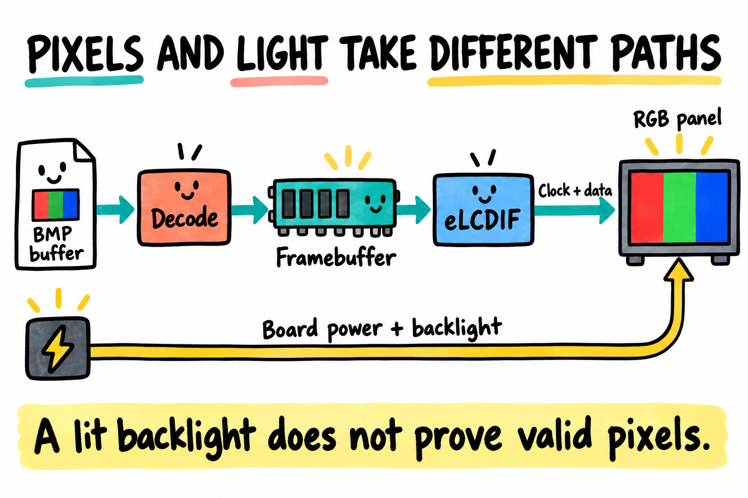
Image bytes, scanout pixels, and panel light follow different paths. A black screen can therefore have more than one cause. The drawing is a data-flow model, not a carrier schematic or proof of display operation.
24I.2 Files changed in this chapter
File or area |
Responsibility |
|---|---|
|
DM video, MXS/eLCDIF driver, BMP formats, filesystem commands |
|
Verified display timing/pinmux description |
Board display integration |
Rail, reset, and backlight sequencing, before the required operation |
|
Optional splash command, without replacing safety policy |
Identified boot partition |
Trusted, validated |
This extends the same board port. It does not create a second board or change its ROM/DCD boot path. These are modern-port filenames, not vendor target names. Establish UART1 and SD/eMMC first; then add video with a matched panel, verified DDR, display clocks, memory reservations, and power.
The guide lists ATK RGB module IDs such as 4342 (480 x 272), 4384/7084
(800 x 480), 7016 (1024 x 600), and 1018 (1280 x 800). Choose by the fitted
module, not by screen diagonal alone. The public vendor eMMC board source
currently defines a TFT7016 mode and detect = NULL: neither a default
panel string nor that table proves automatic MINI panel-ID detection.
Its helper also treats GPIO5_IO09 as LCD reset, whereas the supplied core
labels SNVS_TAMPER9 nWDOG in the shared reset network. Review that difference
before enabling or migrating the helper; do not toggle it as a harmless
independent panel reset. Keep the exact matched mode and observed baseline
behavior as comparison evidence, rather than advertising every kit screen
as supported by the same binary.
24I.4 Add the LCD to the U-Boot Device Tree
The MXS driver reads an LCDIF display phandle, then bits-per-pixel and the
first display-timings entry in that referenced node. In this version it
does not use bus-width to choose the wire format or native-mode to select
another timing entry. Match its actual parser, not just a Linux binding.
The following is an 800 x 480 timing-format example, not the vendor’s TFT7016 mode or a timing selected from MINI panel-ID lines. For a fitted 4384/7084 module, compare every clock/porch/polarity with its own timing specification; sharing a resolution does not qualify these values. For 7016 or another module, replace the geometry too. It assumes 24-bit RGB wiring and active-high DE:
&lcdif {
    pinctrl-names = "default";
    pinctrl-0 = <&pinctrl_lcdif>;
    display = <&display0>;
    status = "okay";

    display0: display {
        bits-per-pixel = <24>;
        display-timings {
            timing0 {
                clock-frequency = <33000000>;
                hactive = <800>;
                vactive = <480>;
                hfront-porch = <40>;
                hback-porch = <88>;
                hsync-len = <48>;
                vfront-porch = <13>;
                vback-porch = <32>;
                vsync-len = <3>;
                hsync-active = <0>;
                vsync-active = <0>;
                de-active = <1>;
                pixelclk-active = <0>;
            };
        };
    };
};
Supply the board-specific pinctrl_lcdif group under the existing IOMUXC
node. For 24-bit wiring that normally includes LCD_CLK, ENABLE/DE, HSYNC,
VSYNC, and DATA00..23 with the appropriate pad macros. An 18-bit panel needs
its documented signal mapping and driver format; do not arbitrarily remove
six wires. On MINI, retain the SGM3157/boot-strap arrangement described above
and account for the shared reset and BLT_PWM pin ownership.
Pad drive strength and slew are electrical choices, not universal 0x79
settings.
The example’s horizontal total is 800+40+88+48=976 clocks and vertical total
480+13+32+3=528 lines. Divide the pixel clock by their product to obtain the
nominal frame rate. This is arithmetic, not a measured/calibrated clock or a
panel-approved refresh rate. Verify actual clock capability, edge semantics,
and DE polarity; this MXS implementation sets ENABLE polarity high during
setup, so a DE-low panel needs source-level investigation rather than a DT
promise alone.
The driver does not resolve a generic panel/backlight phandle and perform
all module power/reset sequencing for you. GPIO1_IO08 can provide GPIO
enable or PWM1 output according to the matched module’s BLT_PWM contract;
the net name alone does not establish polarity, duty limits or sequencing.
Provide that reviewed integration before probe where needed: stabilize
rails, apply reset timing, prepare valid
scanout, then enable the backlight in the panel-approved order. A
gpio-backlight node on its own is not proof that this path invokes it.
Critical power checks from Chapter 24H must precede the operation they guard,
not merely run later in board_late_init().
24I.5 Prepare the BMP file
Use one trusted, uncompressed Windows-style BMP with a 40-byte DIB header, 24-bit BGR pixels, positive height (bottom-up rows), no palette, and dimensions that fit the verified panel. Start with clear color bars and a border; they make swapped colors and shifted edges visible without a complex logo.
For the 800 x 480 format example, each row is padded to a multiple of four bytes:
row bytes = ((800 * 3 + 3) / 4 rounded down) * 4 = 2400
pixel bytes = 2400 * 480 = 1152000
file bytes = 14 + 40 + 1152000 = 1152054
framebuffer bytes for the driver's 32-bit path = 800 * 480 * 4 = 1536000
These are calculated sizes for that format, not observed output. Inspect the
actual file’s header, offset, dimensions, compression, and total length on the
host. U-Boot’s bmp info reads header fields; it does not fully validate a
file against a supplied buffer length. Do not feed arbitrary recovery-uploaded
BMPs to a bootloader decoder as if it were a hardened image service.
Put the checked file on the identified intended boot partition using the
already approved storage-copy workflow. Do not use a guessed /dev/sdX1
mount/copy recipe. If using Chapter 24G UMS, the host must own the exposed
range exclusively and release it before U-Boot loads the file.
24I.6 Manual U-Boot display test
First establish the image-buffer reservation using bdinfo, the port’s
memory layout, and the video framebuffer reservation. The image buffer must
fit entirely inside qualified DDR and avoid U-Boot relocation/stack/malloc,
control DT, framebuffer, kernel/DTB/initrd ranges, and decompression space.
0x88000000 is not safe merely because it is in DDR: video reserves memory
near the top and the allocation depends on the build and RAM size.
These placeholders must be replaced by the reviewed layout:
pa-mini=> bdinfo
pa-mini=> dm tree
pa-mini=> setenv splashimage <reserved image-buffer start>
pa-mini=> setenv splash_max <reserved buffer size in hexadecimal bytes>
pa-mini=> setenv splashpart <identified MMC device:boot-partition>
pa-mini=> fatsize mmc ${splashpart} splash.bmp
pa-mini=> printenv filesize
Confirm a nonzero file size no larger than splash_max, then load and inspect
it. No host/other target writer may alter the file between size-check and load.
pa-mini=> fatload mmc ${splashpart} ${splashimage} splash.bmp
pa-mini=> bmp info ${splashimage}
pa-mini=> bmp display ${splashimage} 0 0
Require actual successful commands and sensible dimensions/bit depth. A successful display command means the software path accepted the image; the panel observation is another checkpoint. Record both rather than copying an invented success log. If U-Boot console output also targets video, later text or scrolling may overwrite the splash. Retain serial as the debug console; change display console routing only after diagnosing it explicitly.
24I.7 Add the splash command to the default environment
Only after the manual path works, merge this macro with the existing defaults. It deliberately leaves buffer address/size and partition to the reviewed board layout:
#define PA_MINI_SPLASH_ENV \
    "splashfile=splash.bmp\0" \
    "show_splash=if test -n \"${splashimage}\" && " \
        "test -n \"${splash_max}\" && test -n \"${splashpart}\"; then " \
        "if fatsize mmc ${splashpart} ${splashfile}; then " \
            "if itest ${filesize} -gt 0 && itest ${filesize} -le ${splash_max}; then " \
                "if fatload mmc ${splashpart} ${splashimage} ${splashfile}; then " \
                    "bmp display ${splashimage} 0 0; " \
                "else echo Splash load failed; false; fi; " \
            "else echo Splash exceeds reserved buffer or is empty; false; fi; " \
        "else echo Splash file unavailable; false; fi; " \
    "else echo Splash buffer not configured; false; fi\0"
fatsize produces hexadecimal filesize; itest handles the numeric
comparison. The command bounds the file load, not malformed BMP header reads.
Use only the prevalidated trusted asset. Do not replace this with a truncated
load and then try to decode an incomplete file.
For Chapter 24F’s policy, a reviewed normal-path wrapper is:
normal_with_splash=run show_splash; run boot_selected
bootcmd=run normal_with_splash
Make that the single normal command definition, with matching compiled boot
command settings. Keep altbootcmd and Chapter 24G/H overrides intact.
Do not introduce a new normal_boot=run mmcboot that bypasses A/B selection
or safety. Updating defaults does not replace saved variables; reconcile them
manually without deleting unrelated settings. No saveenv is needed for
initial RAM-only trials.
24I.8 If the display is black
Observation/check |
Next evidence |
|---|---|
Backlight dark |
Approved rail/enable measurement; a flashlight may reveal faint pixels |
File not loaded |
Storage identity, |
Header implausible |
Reinspect trusted host file, do not keep decoding it |
No video device |
Generated config, compatible match, control DT and probe errors |
Lit but blank/shifted panel |
Reset sequence, pinmux, signal routing, clock/porches/polarities |
Wrong colors |
Wire RGB order, framebuffer format, BMP format/conversion |
Image changes after display |
Video-console output or Linux reinitialization |
Corruption elsewhere |
Image/framebuffer/load/decompression memory overlap |
Work outward from a known observation. A lit backlight does not prove pixel traffic, and a framebuffer in RAM does not prove electrical timing. Use only approved probing points and instruments; never change supply voltages to try to make the image brighter.
24I.9 Make the splash optional
run show_splash; run boot_selected intentionally ignores the first command’s
failure and still attempts the recorded normal boot policy. The second
command’s success/failure remains the wrapper’s result. A missing logo does
not choose another slot or mark a candidate good.
For a factory image test, use a different wrapper:
factory_splash=if run show_splash; then echo TEST:SPLASH:COMMAND_OK; else echo TEST:SPLASH:FAIL; false; fi
COMMAND_OK is not a panel inspection PASS. The fixture still needs optical
or electrical evidence if display output is part of acceptance. Avoid an
unconditional trailing success message that hides a failed BMP command.
24I.10 Production choices
Asset location |
Tradeoff |
|---|---|
Boot-partition BMP |
Easy replacement, but file validity/access must be controlled |
Embedded asset |
Fixed with the U-Boot build; requires a defined decode/display integration |
Verified FIT/partition |
Authentication can cover the asset, only if it is actually checked before decoding |
A file residing inside a signed container is not automatically verified by
fatload followed by bmp display. Keep image-size validation even when
integrity is authenticated. Optional visual feedback must not weaken the
recovery/power decision or delay watchdog service unpredictably.
24I.11 Key Notes
BMP source data, framebuffer pixels and RGB wires are separate formats. The MXS 24/18-bit output paths use 32-bit framebuffer storage, independent of a 24-bit BMP decoder.
eLCDIF scanout and backlight power are separate paths. The fitted module’s timing, sequencing and BLT_PWM contract determine whether valid RAM pixels become a visible image.
MINI J1 includes shared reset and SGM3157 isolation on display/boot-strap lines. An inherited independent LCD-reset helper is not permission to drive the shared reset network.
U-Boot’s actual parser determines which timing and power properties take effect. A Linux binding or backlight node does not guarantee that the selected bootloader driver consumes it.
Trusted BMP validation and separate image/framebuffer reservations precede decoding.
bmp infoheader output is not a complete bounded-input validation service.The optional splash wrapper can report failure while preserving normal A/B boot, but must not bypass recovery or power vetoes. A displayed logo neither accepts a candidate nor establishes product readiness.
Linux owns its own display initialization after handoff. Seamless image preservation requires an explicit cross-stage contract, not merely a successful
bmp displaycall.
24I.12 Pitfalls
Backlight equals initialized panel. They are separate paths.
Linux binding equals U-Boot behavior. Read this version’s actual parser.
Missing
BMP_24BPP. Generic BMP support alone is not every source format.Universal timing/pad settings. MINI routing and the actual module determine them.
Ignoring the SGM3157 switches or shared reset. They are part of this board, not optional decoration.
Loading over the framebuffer or kernel. Reserve the complete range first.
Decoding an untrusted/truncated image. Header output is not full validation.
A splash wrapper replacing safety policy. Preserve A/B and both veto paths.
Expecting seamless Linux takeover. Reinitialization is a separate contract.
24I.13 Going deeper
Supplied MINI V2.2 schematic, sheets 1-2, core schematic sheets 5/8, and guide MINI Section 5.4.4 (pp. 267-268): J1 wiring, panel choices, SGM3157 isolation, shared reset, and GPIO1_IO08 backlight control.
Vendor eMMC board display implementation: inspect the configured mode and reset assumptions before migration.
Splash preparation and splash code, for the optional framework rather than this manual path.
The fitted panel’s official timing/electrical specification and the carrier schematic are prerequisites for a hardware example.