Chapter 12: UART driver and printf¶
An LED can tell us that a program reached a checkpoint. It is less helpful when we want the value of a register or the name of the next step. We could invent a blink code, but the board already has a better route to the host: UART1 and its USB-to-serial bridge.
The design starts with character transport, then strings, then a small formatter in front of that transport. Keeping those jobs separate means that a garbled number does not immediately send us back to the pinmux table. The examples explain each layer without requiring a completed serial session.
12.1 Which UART, and on which pins¶
The i.MX6ULL has eight UART controllers, UART1 through UART8. The Point Atom MINI uses UART1 as its debug console. The UART1 TX and RX pads are connected to the board’s integrated USB-to-TTL bridge, which then connects to the host through the USB-TTL or DEBUG USB port described in Chapter 8.
The signal path is:
i.MX6ULL UART1 pads -> onboard USB-TTL bridge -> debug USB connector -> host serial device
No external CP2102, CH340, FTDI adapter, or jumper wiring is needed. The bridge chip may itself be a CH340 or similar device, but it is already installed on the board.
For our purposes:
Module: UART1, base address
0x02020000.Pads:
UART1_TX_DATA(ALT0 = UART1_TX_DATA),UART1_RX_DATA(ALT0 = UART1_RX_DATA).Pad IOMUXC registers:
IOMUXC_SW_MUX_CTL_PAD_UART1_TX_DATAat0x020E0084, RX at0x020E0088. (Verify against your RM.)Daisy-chain register:
IOMUXC_UART1_RX_DATA_SELECT_INPUTat0x020E0624. For theUART1_RX_DATApad used here, the required daisy value is3.
Why RX needs a daisy-chain register¶
Many i.MX6ULL peripheral inputs can arrive through more than one package pad. UART1 RX is one example. Several pads have an alternate function that can feed the UART1 receiver. The UART therefore needs two separate selections:
Pad MUX selection: choose which function the physical pad performs.
Peripheral input selection: choose which eligible pad the UART1 receiver listens to.
The second selection is the daisy-chain register. Despite the name, signals are not passed through devices in a serial chain. It is an input multiplexer inside the SoC:
candidate pad A ----\
candidate pad B -----+--> SELECT_INPUT mux --> UART1 RX logic
UART1_RX_DATA pad ---/
                         ^
                         daisy value selects one path
For our board, both settings are required:
REG(IOMUX_MUX_RX) = 0;  /* ALT0: this pad performs UART1_RX_DATA */
REG(IOMUX_DAISY)  = 3;  /* UART1 listens to this pad's input path */
These two numbers belong to different registers. Daisy value 3 does not mean ALT3. The pad uses ALT0, while the UART input selector uses candidate 3.
The upstream Linux pin-function header describes the same route with this five-value tuple:
MX6UL_PAD_UART1_RX_DATA__UART1_DCE_RX 0x0088 0x0314 0x0624 0 3
The tuple means:
Value |
Meaning |
|---|---|
|
MUX_CTL register offset |
|
PAD_CTL register offset |
|
SELECT_INPUT register offset |
|
pad mux mode, ALT0 |
|
input daisy value |
TX usually does not need this extra selection. Once the TX pad is muxed to UART1 TX, the UART drives that pad outward. RX travels inward, so the SoC must know which possible pad to connect to the receiver.
If the daisy value is wrong, TX can still print correctly while RX receives nothing. A voltage transition may reach the physical RX pad, but the UART receiver is connected internally to a different candidate path.
The UART1 gate is CCM_CCGR5, bits 24-25 (CG12). The baud calculation below needs an 80 MHz module clock. Our driver explicitly selects PLL3’s divided-by-six path and a root divider of one. It assumes the normal direct ROM boot has supplied a running 480 MHz PLL3. It is not a clock recipe for an arbitrary previous program’s state. Chapter 13 follows the wider clock tree.
12.2 Baud rate, the i.MX way¶
Most UART chips compute baud as f_in / (16 × divisor). I.MX is the same shape but with two divisor stages, so it can hit awkward baud rates:
baud = (f_uart_clk / 16) × (UBIR + 1) / (UBMR + 1)
UBIRis a 16-bit numerator register (Baud Rate Numerator).UBMRis a 16-bit denominator register (Baud Rate Modulator).The factor of 16 is the oversampling rate, fixed.
UFCR.RFDIVis an encoded integer divider between the module clock and the reference clock used in this formula. We choose divide by one. Its field value is5, not1.
For our case:
f_uart_clk = 80 MHzTarget baud = 115200
We want
(UBIR + 1) / (UBMR + 1) = 115200 × 16 / 80 000 000 = 0.02304
Multiply the ratio by 25,000: the numerator becomes 576. Both numbers fit the 16-bit registers, giving an exact nominal ratio:
UBIR = 575UBMR = 24999
The calculation is 80,000,000 / 16 * 576 / 25,000 = 115,200. There is no nominal divider error in this choice. The actual clock can still have oscillator error. With other clock/baud combinations, integer register values introduce an error that must be evaluated rather than assuming the UART will correct it. Receiver tolerance depends on both ends and the frame format.
12.3 Register map (the ones we actually use)¶
This is the working register map for the driver. Keep it beside the listing:
Register |
Offset |
Purpose |
|---|---|---|
|
|
Receive data (read) |
|
|
Transmit data (write) |
|
|
Control 1 (enable) |
|
|
Control 2 (TX/RX/8N1) |
|
|
Control 3 (various) |
|
|
Control 4 (DMA off, RX threshold) |
|
|
FIFO control + clock div |
|
|
Status 1 (TRDY = FIFO at/below its configured TX threshold) |
|
|
Status 2 (TXDC = TX complete, RDR = RX data ready) |
|
|
Escape character (we ignore) |
|
|
Escape timer (we ignore) |
|
|
Baud numerator |
|
|
Baud denominator |
|
|
UART test register. The TX FIFO full bit lives here. |
The full list is RM Table 55-3. We will not visit most of them.
The main control and status bits are:
UCR1.UARTEN(bit 0), overall UART enable.UCR2.SRST(bit 0), software reset. Write zero to request reset, then wait for hardware to set it again. Writing one does not manually release it.UCR2.TXEN/UCR2.RXEN(bits 2 / 1), transmitter and receiver enables.USR1.TRDY(bit 13), the transmit FIFO has reached its configured refill threshold. It is not the same test asUTS.TXFULL(bit 4).USR2.RDR(bit 0), receive data ready.
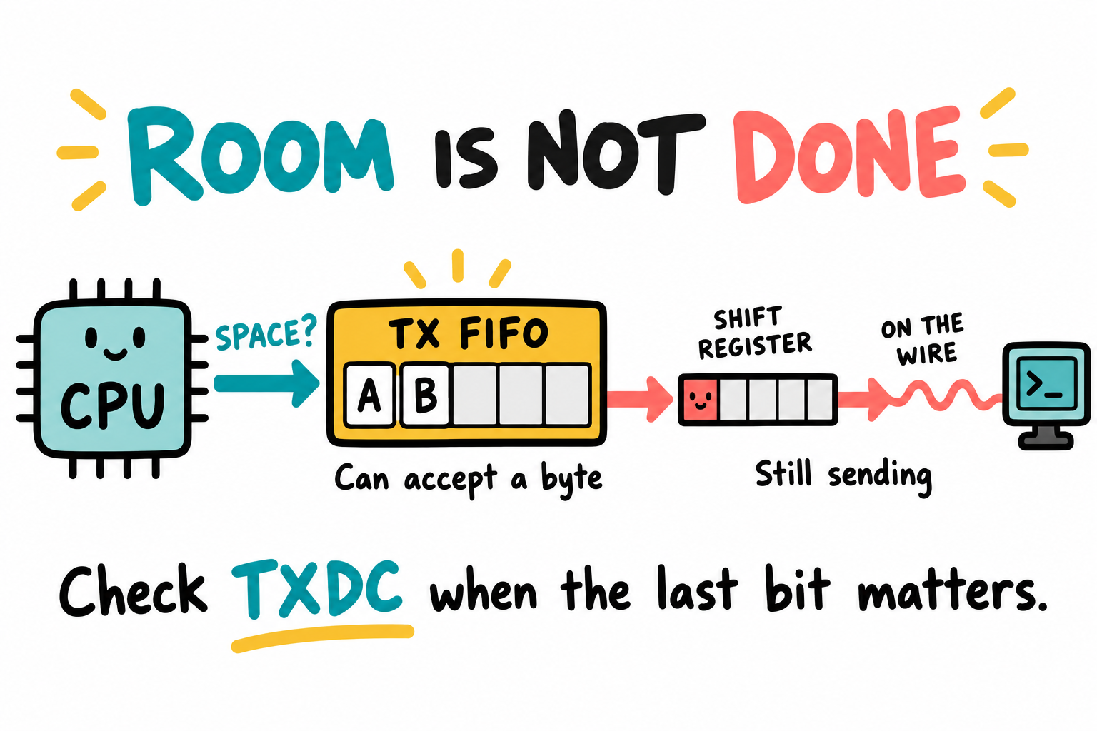
Room in the FIFO lets us queue another byte. It does not say the last byte has left the pin. UTS.TXFULL answers the space question. USR2.TXDC answers the completion question.¶
12.4 The driver, top to bottom¶
Copy the four Chapter 10 project files into ~/imx6ull/src/ch12-uart-printf using your editor or file manager. Keep a working copy of Chapter 10. Save uart.h, uart.c and mini_printf.c beside them, then replace main.c with Section 12.6’s listing. Add uart.o mini_printf.o to OBJS in the copied Makefile. Its -lgcc supplies the integer-division helpers used by the formatter.
uart.h:
#ifndef UART_H
#define UART_H

#include <stdint.h>

void uart_init(void);
void uart_putc(char c);
void uart_puts(const char *s);
int  uart_getc(void);     /* -1 if no data */

#endif
uart.c:
#include "uart.h"

#define REG(addr) (*(volatile uint32_t *)(addr))

#define UART1_BASE   0x02020000
#define UART_URXD    (UART1_BASE + 0x000)
#define UART_UTXD    (UART1_BASE + 0x040)
#define UART_UCR1    (UART1_BASE + 0x080)
#define UART_UCR2    (UART1_BASE + 0x084)
#define UART_UCR3    (UART1_BASE + 0x088)
#define UART_UCR4    (UART1_BASE + 0x08C)
#define UART_UFCR    (UART1_BASE + 0x090)
#define UART_USR1    (UART1_BASE + 0x094)
#define UART_USR2    (UART1_BASE + 0x098)
#define UART_UBIR    (UART1_BASE + 0x0A4)
#define UART_UBMR    (UART1_BASE + 0x0A8)
#define UART_UTS     (UART1_BASE + 0x0B4)

#define CCM_CCGR5    0x020C407C
#define CCM_CSCDR1   0x020C4024
#define IOMUX_MUX_TX 0x020E0084
#define IOMUX_MUX_RX 0x020E0088
#define IOMUX_PAD_TX 0x020E0310
#define IOMUX_PAD_RX 0x020E0314
#define IOMUX_DAISY  0x020E0624

#define UTS_TXFULL   (1u << 4)
#define USR2_RDR     (1u << 0)

void uart_init(void)
{
    /* 1.  Gate the clock to UART1.  CG12 (bits 24-25) of CCGR5 = 0b11. */
    REG(CCM_CCGR5) |= (3u << 24);
    REG(UART_UCR1) = 0;
    /* Shared UART root: PLL3/6, divider 1. No other UART is in use here. */
    REG(CCM_CSCDR1) &= ~0x7Fu;

    /* 2.  Pinmux: ALT0 on both TX and RX pads. */
    REG(IOMUX_MUX_TX) = 0;
    REG(IOMUX_MUX_RX) = 0;
    REG(IOMUX_PAD_TX) = 0x000010B0;   /* push-pull, keeper enabled */
    REG(IOMUX_PAD_RX) = 0x000130B1;   /* pull enabled, fast slew */
    REG(IOMUX_DAISY)  = 3;            /* select UART1_RX_DATA input path */

    /* 3.  Soft-reset the UART (SRST is active-low: clear to assert). */
    REG(UART_UCR2) = 0;
    while (!(REG(UART_UCR2) & 1)) { /* hardware completes reset */ }

    /* 4.  Disable while configuring. */
    REG(UART_UCR1) = 0;

    /* 5. No hardware flow control; 8N1; RX+TX enable. */
    REG(UART_UCR2) = (1u << 14)   /* IRTS (ignore RTS) */
                   | (1u << 5)    /* WS = 8 data bits */
                   | (1u << 2)    /* TXEN */
                   | (1u << 1)    /* RXEN */
                   | (1u << 0);   /* writing 1 leaves SRST unchanged */

    /* 6. RM 55.15.5 requires RXDMUXSEL for this chip's muxed input. */
    REG(UART_UCR3) = (1u << 2);

    /* 7.  No DMA, no escape detection. */
    REG(UART_UCR4) = 0;           /* keep receive-ready and other IRQs disabled */

    /* 8.  FIFO control: RX trigger = 1, TX trigger = 2, RFDIV = /1.
          UFCR fields:
            RXTL  bits  5:0     RX FIFO trigger level
            RFDIV bits  9:7     reference freq divider (0b101 = /1 on i.MX6ULL)
            TXTL  bits 15:10    TX FIFO trigger level
    */
    REG(UART_UFCR) = (2u << 10)         /* TXTL = 2 */
                   | (5u << 7)          /* RFDIV = /1 */
                   | (1u << 0);         /* RXTL = 1 */

    /* 9. 115200 from an 80 MHz reference. Write UBIR before UBMR. */
    REG(UART_UBIR) = 575;
    REG(UART_UBMR) = 24999;

    /* 10. Enable UART. */
    REG(UART_UCR1) = (1u << 0);    /* UARTEN */
}

void uart_putc(char c)
{
    while (REG(UART_UTS) & UTS_TXFULL) { /* spin while FIFO is full */ }
    REG(UART_UTXD) = (uint8_t)c;
}

void uart_puts(const char *s)
{
    while (*s) {
        if (*s == '\n') uart_putc('\r');
        uart_putc(*s++);
    }
}

int uart_getc(void)
{
    if (!(REG(UART_USR2) & USR2_RDR)) return -1;
    return (int)(REG(UART_URXD) & 0xFF);
}
Follow the initialization in groups: clock and pads, controller reset, frame settings, baud, then enable. Three details explain common half-working results:
Write UBIR before UBMR. RM 55.5 requires both writes in that order to update the rate multiplier. Reversing them does not produce one predictable percentage error.
The
\nto\r\ntranslation inuart_putssupplies both a new line and a return to column zero without depending on a particular terminal mapping.UCR3.RXDMUXSEL = 1is a requirement in the register description, not an unexplained erratum workaround. It is separate from the IOMUX daisy value.
This small driver has blocking transmit/reset waits, no timeout and no receive-error reporting. A stopped reference clock can leave it waiting forever. It illustrates an early console, not a fault-tolerant production interface.
12.5 A small printf¶
The formatter is deliberately limited so we can follow a number from its digits to uart_putc(). A maintained formatter with appropriate tests is a better starting point for a product. This one accepts only the formats listed below and returns zero rather than a standard printf character count.
mini_printf.c:
#include <stdarg.h>
#include <stdint.h>
#include "uart.h"

static void emit_char(char c)            { uart_putc(c); }
static void emit_str(const char *s)
{
    if (!s) s = "(null)";
    while (*s) emit_char(*s++);
}

static void emit_uint(unsigned long v, unsigned base, int width, char pad,
                      int negative)
{
    char buf[sizeof(v) * 8];
    const char *digits = "0123456789abcdef";
    int i = 0;
    if (v == 0) buf[i++] = '0';
    while (v) { buf[i++] = digits[v % base]; v /= base; }
    int padding = width - i - negative;
    if (pad == ' ') while (padding-- > 0) emit_char(' ');
    if (negative) emit_char('-');
    if (pad == '0') while (padding-- > 0) emit_char('0');
    while (i--) emit_char(buf[i]);
}

static void emit_int(int v, int width, char pad)
{
    unsigned magnitude = v < 0 ? 0u - (unsigned)v : (unsigned)v;
    emit_uint(magnitude, 10, width, pad, v < 0);
}

int mini_vprintf(const char *fmt, va_list ap)
{
    while (*fmt) {
        if (*fmt != '%') { emit_char(*fmt++); continue; }
        fmt++;                                 /* skip '%' */
        char pad = ' ';
        int  width = 0;
        if (*fmt == '0') { pad = '0'; fmt++; }
        /* Cap field width at 64 without writing padding into the digit buffer. */
        while (*fmt >= '0' && *fmt <= '9') {
            width = width * 10 + (*fmt++ - '0');
            if (width > 64) width = 64;
        }
        if (!*fmt) { emit_char('%'); break; }

        switch (*fmt) {
        case 'c':  emit_char((char)va_arg(ap, int));         break;
        case 's':  emit_str(va_arg(ap, const char *));       break;
        case 'd':  emit_int (va_arg(ap, int),  width, pad);  break;
        case 'u':  emit_uint(va_arg(ap, unsigned), 10, width, pad, 0); break;
        case 'x':  emit_uint(va_arg(ap, unsigned), 16, width, pad, 0); break;
        case 'p':  emit_str("0x"); emit_uint((uintptr_t)va_arg(ap, void*), 16,
                                          sizeof(uintptr_t) * 2, '0', 0); break;
        case '%':  emit_char('%');                           break;
        default:   emit_char('%'); emit_char(*fmt);          break;
        }
        if (*fmt) fmt++;
    }
    return 0;
}

int printf(const char *fmt, ...)
{
    va_list ap;
    va_start(ap, fmt);
    int r = mini_vprintf(fmt, ap);
    va_end(ap);
    return r;
}
Features we support: %c %s %d %u %x %p %%. Numeric field width up to 64, space/zero padding and negative %d. Width is ignored for strings and characters. Padding is emitted separately from the digit buffer, so a wide field cannot overflow that buffer. Unsigned subtraction handles INT_MIN without signed-negation overflow.
Features we do not support: %f (we have no floats in the kernel of this book), %lld, %ll, locales, precision (%.5s), left-justification (%-5d), %n. Cover them when you need them.
Variadic arguments follow C’s default promotions. On this target, an unsigned char or unsigned short promotes to int, because int can represent all its values. Cast a small value to unsigned when passing it to %u or %x. Pass an int to %d and a void * to %p. Equal type sizes do not make an arbitrary va_arg type correct. Keep length modifiers such as %lu out of this formatter’s calls.
12.6 main() that actually says hello¶
#include "uart.h"
int printf(const char *fmt, ...);

int main(void)
{
    uart_init();

    printf("\r\nHello, i.MX6ULL bare-metal world!\r\n");
    printf("CPU running at boot-default clock.\r\n");
    printf("This text travels at 115200 baud.\r\n");
    printf("printf supports %%d=%d %%u=%u %%x=0x%08x %%s=\"%s\" %%c=%c\r\n",
           -42, 0xCAFEu, 0xDEADBEEFu, "ready", 'Z');

    /* Echo loop so you can confirm RX works. */
    printf("\r\nType characters. They will echo back.\r\n> ");
    for (;;) {
        int c = uart_getc();
        if (c >= 0) uart_putc((char)c);
    }
}
Keep the board’s integrated USB-TTL port connected. In one host terminal, open the serial device found in Chapter 8:
$ sudo picocom -b 115200 /dev/ttyUSB0
If the bridge appeared as /dev/ttyACM0, use that path instead. This connection carries UART text. The separate USB-OTG connection carries SDP commands from uuu.
In another host terminal, build and load the image through the board’s USB-OTG port:
$ . ~/imx6ull/scripts/env.sh
$ cd ~/imx6ull/src/ch12-uart-printf
$ make
$ python3 ~/imx6ull/scripts/mkimx.py led.bin led.imx
$ sudo "$IMX6ULL_HOME/build/mfgtools/uuu/uuu" led.imx
In the terminal connected through the integrated USB-TTL bridge:
Hello, i.MX6ULL bare-metal world!
CPU running at boot-default clock.
This text travels at 115200 baud.
printf supports %d=-42 %u=51966 %x=0xdeadbeef %s="ready" %c=Z

Type characters. They will echo back.
> hello
A transport-only case consists of uart_init(); uart_puts("UART only\n"); followed by an infinite loop. It bypasses the formatter, separating transport failures from format handling. The transcript above is representative, not a recorded board result. Terminal local echo must be off before returned characters can serve as evidence of the RX path.
12.7 Why polled UART, not interrupt-driven¶
We are deliberately using polling. Reasons:
No interrupt controller yet. The GIC will be set up properly in Chapter 15.
Polling is sufficient for this small console. An 8N1 character needs ten bit periods, about 87 microseconds at 115200 baud. The FIFO can accept several bytes sooner, but a long stream is limited by that wire rate. This is not a worst-case bound on our wait loops, especially if the clock stops.
Polling shows the status bits directly. The interrupt version follows the same hardware flow, but the FIFO threshold triggers an ISR.
Chapter 15 uses an interrupt-driven echo to explain how the GIC changes event delivery without changing the UART’s data path.
12.8 Key Notes¶
UART1 transport and number formatting are separate interfaces. The integrated USB-TTL bridge carries console bytes, while USB-OTG carries ROM downloader commands.
RX requires both the pad’s ALT selection and the peripheral’s input daisy selection. Correct TX output does not establish a working RX route.
Baud derives from the UART reference clock, encoded RFDIV and UBIR/UBMR ratio, not the ARM core rate. An exact nominal ratio still leaves oscillator error and receiver tolerance to consider.
FIFO space permits another queued byte. It does not mean transmission is complete on the wire, so clock or power transitions need the appropriate completion condition.
Polling simplifies the early console but occupies the CPU and can wait indefinitely if the clock stops. Without flow control, incoming data can also exceed the receiver’s service capacity.
The formatter supports a defined subset of formats and requires matching promoted argument types. Unsupported formats are an interface limitation, not a UART fault.
Chip-identity diagnostics use documented OCOTP shadow-register reads under their clock/access requirements. They do not require programming registers or fuse writes.
12.9 Pitfalls¶
Wrong RFDIV in UFCR. Setting
RFDIV = 0divides by 6, not 1. Symptom: baud rate is six times too slow. The encoding is: 000=/6, 001=/5, 010=/4, 011=/3, 100=/2, 101=/1. Always0b101.Reset never completes. After requesting reset, wait for hardware to restore
SRST. Writing one cannot force completion. Check the module clock if the loop never exits.Wrong daisy-chain (SELECT_INPUT). Symptom: TX works through the onboard bridge, but typed characters do not echo.
UART1_RX_DATA_SELECT_INPUTmust select the pad physically connected to the bridge.Using the wrong USB connector. The USB-TTL port appears as
/dev/ttyUSBxor/dev/ttyACMxand carries console text. The USB-OTG port appears as the i.MX6ULL SDP device and is used byuuu.CRLF versus LF. Terminal mappings can differ.
uart_puts()inserts\rbefore\n, while this formatter emits characters directly, so its example strings use explicit\r\n. Do not insert an extra carriage return in both layers.printfwithfloats. Compiles, runs, and prints wrong output because we never wrote%f. Do not pass floats to thisprintf.UBIR after UBMR. Discussed in §12.4. Write UBIR first.
Forgot the CCGR. If the UART is silent, check the clock gate before debugging the UART registers.
12.10 Going deeper¶
IMX6ULLRM Chapter 55: UART. Read once cover-to-cover. You’ll come back.
AN3956: Configuring the i.MX UART Module. Concise. Useful.
mpaland/printfat<https://github.com/mpaland/printf>, an MIT-licensed formatter to evaluate with your own tests and required format support.The 16550 UART datasheet: every embedded engineer should read this once. It’s the platonic UART.
Linux source:
drivers/tty/serial/imx.c: the same hardware, the same registers, vastly more sophisticated driver. Read it after Chapter 12 here. You’ll recognize every bit.
Text output gives us a way to report the next investigation. In Chapter 13 we trace its clock source and the CPU clock through CCM, the Clock Controller Module, rather than assuming the ROM’s choices suit every peripheral.