Chapter 15: Exceptions and the GIC
A received character can be sitting in the UART FIFO while the CPU sleeps. To wake the program, three things must agree: the UART must request an interrupt, the GIC must route it, and the CPU must have a usable vector and stack. We will follow one character through that path.
This is a single-core, non-nested, Secure SVC/IRQ, Group-0 IRQ teaching configuration for the i.MX6ULL GIC-400 (GICv2). SVC mode alone does not prove Secure state. Confirm the boot/handoff policy before using these writes; they are not a drop-in Non-secure, Hyp, Monitor, RTOS, or Linux initializer. IRQ routing must enter IRQ mode rather than Monitor/Hyp. The program owns the controller exclusively and begins without active IRQs.
15.1 What is different from Cortex-M
On Cortex-M, exception entry stacks core registers on the interrupted context’s stack; the handler itself uses MSP. The vector slots contain handler addresses (apart from the initial SP), and EXC_RETURN tells hardware how to return.
On Cortex-A7, the hardware saves CPSR into SPSR_irq, banks IRQ SP/LR, and chooses a vector instruction. It does not save the shared general registers. Software must preserve them and perform an exception return.
A C ISR is an ordinary function behind our assembly wrapper. The compiler does not know that its caller represents an interrupted program. We must provide a valid AAPCS stack and preserve anything the handler can clobber.
15.2 The exception vector table
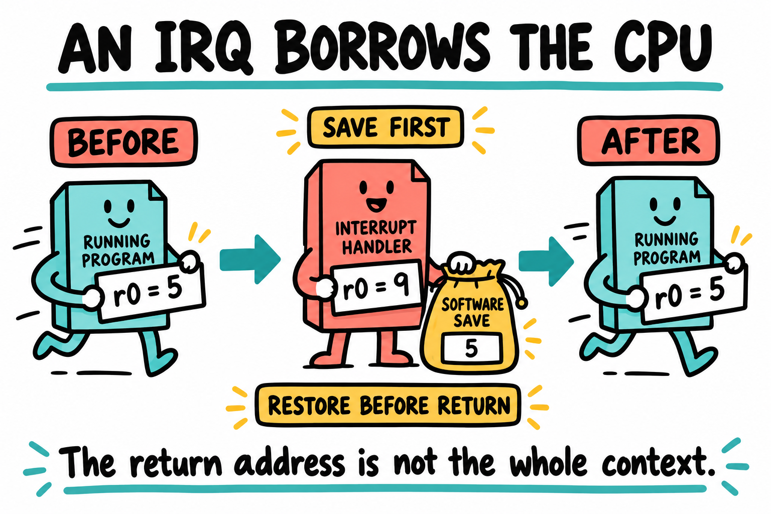
Returning to the right instruction is not enough if its registers have changed. The saved pouch represents our assembly wrapper’s work. Cortex-A7 does not automatically stack these shared registers on IRQ entry.
For our ARM-state exception policy, the vector entries are eight instructions, four bytes each, with a 32-byte-aligned base.
Offset |
Exception |
Cause |
|---|---|---|
|
Reset |
CPU reset vector; ROM normally owns actual reset |
|
Undefined instruction |
Unsupported instruction |
|
SVC |
|
|
Prefetch abort |
Instruction-fetch fault |
|
Data abort |
Data-access fault |
|
Reserved |
Unused vector slot |
|
IRQ |
Routed interrupt request |
|
FIQ |
Fast interrupt request |
A branch or PC-relative load of a handler address is common. This is not the Cortex-M function-pointer table.
With SCTLR.V=0, VBAR supplies the normal vector base; historical low
vectors correspond to VBAR=0. SCTLR.V=1 selects high vectors at
0xFFFF0000 instead. The security state selects the corresponding banked
VBAR. Hyp and Monitor have separate vector-base mechanisms.
Setting VBAR alone is therefore insufficient. Section 15.4 selects ARM-state, little-endian exceptions and clears high-vector selection. With the MMU off, our VBAR value is a physical address.
15.3 The new vector table
vectors.S is a complete assembly module. Its first instruction remains
b _start, compatible with Chapter 10’s ENTRY(_vectors) and IVT entry
at 0x00908000. Hardware reset still enters ROM; this first slot also
serves our image’s software entry.
    .syntax unified
    .cpu cortex-a7
    .arm
    .section .vectors, "ax"
    .balign 32
    .global _vectors
    .type _vectors, %function
_vectors:
    b       _start
    ldr     pc, =undef_handler
    ldr     pc, =svc_handler
    ldr     pc, =prefetch_handler
    ldr     pc, =data_handler
    ldr     pc, =unused_handler
    ldr     pc, =irq_entry
    ldr     pc, =fiq_handler
    .size _vectors, . - _vectors
    .ltorg                          @ handler literals follow all eight slots

    .text
undef_handler:
prefetch_handler:
data_handler:
unused_handler:
svc_handler:
fiq_handler:
    b       .                       @ fail-stop; no C call or stack required

    .global irq_entry
    .type irq_entry, %function
irq_entry:
    sub     lr, lr, #4              @ architectural IRQ resume address
    srsdb   sp!, #0x12              @ {resume PC, SPSR_irq} on IRQ stack
    push    {r0-r12, lr}            @ 56 bytes; total frame = 64 bytes
    bl      c_irq_dispatch          @ stays in IRQ mode, IRQs still masked
    pop     {r0-r12, lr}
    rfeia   sp!                     @ restore PC and CPSR from return frame
    .size irq_entry, . - irq_entry
The return frame is eight bytes, followed by 56 bytes of registers. Starting with an aligned IRQ SP, the C call is eight-byte aligned even if the interrupted SVC function’s SP was only four-byte aligned at that point. The SVC stack and banked SVC LR are never touched.
For an IRQ, LR_irq - 4 is the architectural resume address. Do not
derive it from the PC value visible in a debugger or describe every IRQ as
retrying an instruction. RFE restores both execution address and saved CPSR,
including flags, mode, ARM/Thumb state, and the old interrupt mask.
This wrapper saves core registers only. Compile all reachable ISR code
with -mcpu=cortex-a7 -marm -mfloat-abi=soft -mgeneral-regs-only; do not call
FP/NEON routines or libraries with a mismatched ABI. IRQ nesting is disabled,
FIQs remain masked, and fault handlers halt. There is no scheduler/context
switch or general exception recovery here.
15.4 Setting up VBAR and a separate IRQ stack
Integrate this startup fragment before any IRQ unmask, after establishing Chapter 10’s MMU/data-cache policy. Enter it in privileged Secure SVC, ARM state; the existing SVC stack must already be initialized.
    cpsid   if
    cps     #0x12
    ldr     sp, =_irq_stack_top
    cps     #0x13

    mrc     p15, 0, r0, c1, c0, 0
    bic     r0, r0, #(1 << 13)      @ SCTLR.V=0: use VBAR
    bic     r0, r0, #(1 << 30)      @ SCTLR.TE=0: ARM-state exception entry
    bic     r0, r0, #(1 << 25)      @ SCTLR.EE=0: little-endian exceptions
    mcr     p15, 0, r0, c1, c0, 0
    isb

    dsb     sy
    mov     r0, #0
    mcr     p15, 0, r0, c7, c5, 0  @ ROM may leave I-cache enabled
    mcr     p15, 0, r0, c7, c5, 6  @ synchronize branch predictor state
    dsb     sy
    ldr     r0, =_vectors
    mcr     p15, 0, r0, c12, c0, 0
    isb
This does not disable I-cache or change the other SCTLR controls. If vectors were written through a data cache, clean their bytes to the required point before instruction invalidation. Our integration policy has MMU/D/L2 disabled; do not silently apply it to a different state.
Inside the existing linker SECTIONS, retain the first-position
KEEP(*(.vectors)). Add this linker fragment after BSS and outside the
existing SVC stack reservation:
.irq_stack (NOLOAD) : ALIGN(8) {
    _irq_stack_bottom = .;
    . += 4096;
    _irq_stack_top = .;
} > OCRAM
ASSERT((_irq_stack_top & 7) == 0, "IRQ stack must be 8-byte aligned")
ASSERT(_irq_stack_top <= 0x00920000, "IRQ stack exceeds owned OCRAM")
ASSERT(_irq_stack_top <= _stack_limit, "IRQ stack overlaps SVC stack")
Keep the original load-end assertion at 0x00918000, the SVC stack’s
4 KiB reservation/assertions, and non-overlap checks for both stacks.
NOLOAD does not allocate more physical RAM. Use the map to verify all
reservations; a 4 KiB IRQ stack is a budget, not a measured worst case.
15.5 The GIC v2 distributor + CPU interface
GIC-400 exposes two regions:
Distributor,
0x00A01000: enable, grouping, target, priority, trigger configuration, and pending/active state.CPU interface,
0x00A02000: priority filtering, acknowledge, EOI.
Distributor (GICD_*)
Register |
Offset |
Purpose |
|---|---|---|
CTLR |
|
Group enable controls; view depends on security |
TYPER |
|
Implemented interrupt register range |
IGROUPRn |
|
Secure grouping: 0 = Group 0 |
ISENABLERn |
|
Write-one enable |
ICENABLERn |
|
Write-one disable |
ISPENDRn / ICPENDRn |
|
Pending state / write-one clear |
IPRIORITYR byte |
|
Priority byte per interrupt |
ITARGETSR byte |
|
CPU target mask for SPIs |
ICFGRn |
|
Two bits per INTID; bit 1 selects edge vs level |
CPU Interface (GICC_*)
Register |
Offset |
Purpose |
|---|---|---|
CTLR |
|
Interface/group enable, IRQ/FIQ and EOI policy |
PMR |
|
Only priorities numerically less than PMR pass |
BPR |
|
Group/subpriority split; implemented resolution is limited |
IAR |
|
Read acknowledges one interrupt, returns a token |
EOIR |
|
Write matching acknowledge token |
RPR / HPPIR |
|
Running/highest-pending priority |
The selected policy sets Group 0, enables it in both blocks, leaves FIQEn
clear so Group 0 arrives as IRQ, and leaves split EOI mode off. Another
security policy needs different access/group handling, not just cpsie i.
The path is: peripheral condition -> pending SPI -> priority/target filter -> CPU IRQ exception -> IAR read -> peripheral service -> source deassertion -> EOI -> exception return. Clearing GIC pending alone does not clear a level-sensitive peripheral condition.
15.6 GIC bring-up code
These are complete modules for the policy above, but not a standalone boot
image. Add gic.o and vectors.o to Chapter 10’s project, replace its
placeholder vector module rather than linking two _vectors definitions,
and integrate section 15.4. If the placeholder is inside startup.S, remove
only its old .vectors block, retaining _start and runtime initialization.
BSS clearing initializes the handler table.
gic.h:
#ifndef GIC_H
#define GIC_H
#include <stdint.h>
typedef void (*irq_handler_t)(void);
void gic_init(void);
void gic_register(uint32_t irq, irq_handler_t fn);
void gic_enable_irq(uint32_t irq);
void gic_disable_irq(uint32_t irq);
void c_irq_dispatch(void);
static inline void irq_enable(void)
{
    __asm__ volatile ("dsb sy\n\tcpsie i\n\tisb" ::: "memory");
}
static inline void irq_disable(void)
{
    __asm__ volatile ("cpsid i" ::: "memory");
}
#endif
gic.c:
#include "gic.h"
#define REG(a) (*(volatile uint32_t *)(uintptr_t)(a))
#define BYTE(a) (*(volatile uint8_t *)(uintptr_t)(a))
#define GICD 0x00A01000u
#define GICC 0x00A02000u
#define MAX_IRQ 192u
static irq_handler_t handlers[MAX_IRQ];
static uint32_t num_lines;

void gic_init(void)
{
    irq_disable();                     /* FIQ must already be masked */
    REG(GICC + 0x000) = 0;
    REG(GICD + 0x000) = 0;
    __asm__ volatile ("dsb sy" ::: "memory");
    num_lines = ((REG(GICD + 0x004) & 31u) + 1u) * 32u;
    if (num_lines > MAX_IRQ) num_lines = MAX_IRQ;
    for (uint32_t i = 0; i < num_lines; i++) handlers[i] = 0;
    /* Disable PPIs; SGIs are not used by this example. */
    REG(GICD + 0x180) = 0xFFFF0000u;
    REG(GICD + 0x280) = 0xFFFF0000u;
    REG(GICD + 0x080) = 0;              /* Secure Group 0 */
    for (uint32_t i = 32; i < num_lines; i += 32) {
        REG(GICD + 0x180 + 4u * (i / 32u)) = 0xFFFFFFFFu;
        REG(GICD + 0x280 + 4u * (i / 32u)) = 0xFFFFFFFFu;
        REG(GICD + 0x080 + 4u * (i / 32u)) = 0;
    }
    for (uint32_t i = 32; i < num_lines; i++) {
        BYTE(GICD + 0x400 + i) = 0xA0;
        BYTE(GICD + 0x800 + i) = 1;     /* CPU0 */
    }
    /* All SPIs disabled: level-sensitive defaults for our UART/EPIT. */
    for (uint32_t i = 32; i < num_lines; i += 16)
        REG(GICD + 0xC00 + 4u * (i / 16u)) = 0;
    REG(GICC + 0x004) = 0xFF;
    REG(GICC + 0x008) = 0;
    __asm__ volatile ("dsb sy" ::: "memory");
    REG(GICD + 0x000) = 1;             /* EnableGrp0 */
    REG(GICC + 0x000) = 1;             /* Group0 IRQ, combined EOI */
    __asm__ volatile ("dsb sy\n\tisb" ::: "memory");
}

void gic_register(uint32_t irq, irq_handler_t fn)
{
    if (irq >= 32 && irq < num_lines) handlers[irq] = fn;
}

void gic_enable_irq(uint32_t irq)
{
    if (irq >= 32 && irq < num_lines) {
        __asm__ volatile ("dsb sy" ::: "memory");
        REG(GICD + 0x100 + 4u * (irq / 32u)) = 1u << (irq & 31u);
    }
}

void gic_disable_irq(uint32_t irq)
{
    if (irq >= 32 && irq < num_lines)
        REG(GICD + 0x180 + 4u * (irq / 32u)) = 1u << (irq & 31u);
}

void c_irq_dispatch(void)
{
    uint32_t iar = REG(GICC + 0x00C);
    uint32_t irq = iar & 0x3FFu;
    if (irq >= 1020) return;            /* special IDs: no normal EOI */
    if (irq >= 32 && irq < num_lines && handlers[irq])
        handlers[irq]();
    else
        gic_disable_irq(irq);           /* quarantine an unhandled SPI */
    __asm__ volatile ("dsb sy" ::: "memory"); /* peripheral clear before EOI */
    REG(GICC + 0x010) = iar;            /* preserve complete IAR token */
    __asm__ volatile ("dsb sy" ::: "memory");
}
Register/unregister and enable/disable sources only with CPU IRQs masked in this simple API. It supports SPIs, not SGI messaging or generic PPIs. It does not reset inherited active interrupts; use a clean, approved boot state rather than applying it under an existing interrupt owner.
Priority/target accesses are bytes. The hardware determines the number of implemented priorities and INTIDs; our handler table caps the supported range. PMR=0xFF admits the chosen 0xA0 priority, not literally every possible priority value.
15.7 Hooking up the UART1 IRQ
RM Table 3-1 lists UART1 as SPI offset 26, so its GIC INTID is
32 + 26 = 58. Add 32 only to SPI offsets, not to an already absolute
INTID or a PPI number.
The following is a fragment inside Chapter 12’s UART implementation,
where its private register definitions are visible. Export the install
function in uart.h. Preserve the 80 MHz UART root prerequisite,
UCR4=0 polling baseline, and exact 115200 baud settings; do not globally
change unrelated UART control bits.
#include "gic.h"
static volatile uint32_t rx_count;

static void uart1_isr(void)
{
    while (REG(UART_USR2) & (1u << 0)) { /* RDR: data available */
        uint32_t rx = REG(UART_URXD);
        uart_putc((int)(rx & 0xFFu));    /* deliberately polling echo */
        rx_count++;
    }
}

void uart1_install_isr(void)
{
    /* CPU IRQs masked; uart_init() and gic_init() already completed. */
    REG(UART_UCR1) &= ~(1u << 9);       /* RRDYEN off during setup */
    REG(UART_UFCR) = (REG(UART_UFCR) & ~0x3Fu) | 1u; /* RXTL=1 */
    gic_register(58, uart1_isr);
    gic_enable_irq(58);
    REG(UART_UCR1) |= 1u << 9;          /* RRDYEN */
}
RX-ready depends on UFCR.RXTL, not merely RDR. RXTL=1 makes one received byte enough to trigger. Reading URXD drains the FIFO and removes the level condition; do not write a fictitious W1C receive-ready bit. A production receiver must inspect URXD error flags and handle overruns; this echo drops that information deliberately.
Main-body fragment after vectors/stacks and UART are ready:
gic_init();
printf("Interrupt-driven echo\r\n"); /* finish foreground TX first */
uart1_install_isr();
irq_enable();
for (;;) __asm__ volatile ("wfi" ::: "memory");
WFI is a wait hint; an interrupt or another permitted wake condition can complete it. The loop has no foreground work, so an interrupt immediately before WFI does not lose queued main-thread work. A queue-based application needs a proper check-and-sleep protocol.
Polling TX inside the ISR is acceptable only for this bounded-rate demo. IRQs remain masked during echo, so it delays every other IRQ. Do not share an unprotected printf/TX stream with foreground code after enabling it.
15.8 What happens when you type a character
UART1 shifts in the byte. The FIFO reaches RXTL=1 and RRDY is asserted.
RRDYEN enables its level-sensitive interrupt request.
GIC sees SPI 26 / INTID 58, enabled and targeted to CPU0.
Priority 0xA0 passes PMR=0xFF and the running-priority/group filters.
CPU saves CPSR to SPSR_irq, selects IRQ SP/LR, and enters VBAR+0x18.
The vector load reaches irq_entry. It saves a 64-byte core/return frame on the IRQ stack and calls the dispatcher without enabling nesting.
IAR acknowledges INTID 58. The dispatcher calls the UART ISR.
The ISR drains URXD and echoes; draining removes the receive-ready source.
The dispatcher orders device writes before writing the full IAR token to EOIR.
The wrapper restores registers; RFE restores the resume PC and CPSR.
This is the hardware/privileged entry path. Linux adds its own entry, IRQ-domain mapping and dispatch machinery. User space does not run the GIC ISR; it can receive data later through a driver and system call.
15.9 Key Notes
Cortex-A7 banks IRQ SP/LR and saves CPSR, but software owns shared-register preservation, stack alignment and exception return. A C handler alone is not an exception-entry interface.
The vector table is executable instructions, not Cortex-M-style handler pointers. VBAR, SCTLR vector/entry controls and the current security state together select the actual path.
UART, GIC distributor, CPU interface and CPSR masks each gate delivery. This example owns the GIC exclusively under a Secure Group-0, non-nested policy. It is not an initializer for an inherited interrupt owner.
A level-sensitive source must be deasserted before EOI. Draining the UART FIFO removes its receive condition, while EOIR consumes the full IAR token. One IRQ can service several bytes, so byte counts and IRQ counts differ.
Polling TX inside the ISR delays other IRQs while nesting is disabled. A queued alternative needs bounded capacity, queue-full policy, critical sections and TX-ready disabling when empty. Neither makes printf reentrant.
WFI changes the waiting behavior, not the interrupt’s ownership. A foreground queue needs a check-and-sleep protocol, and a power-saving claim requires a measurement rather than the presence of WFI alone.
IRQ’s resume rule is exception-specific. The current SVC and abort handlers fail-stop. A returning service needs its own valid wrapper and stack. Address 1 is not a guaranteed fault trigger, and calling C from ABT without a context wrapper is unsafe.
15.10 Pitfalls
VBAR with SCTLR.V still set. High vectors override normal VBAR.
Stale instruction bytes. ROM may leave I-cache active; synchronize a replaced vector table under the actual cache policy.
Wrong security/group view. The Secure Group-0 setup is not a generic Non-secure recipe.
Invalid IRQ stack. Initialize its banked SP and verify its bounds.
FP/NEON in the call tree. Core-register preservation is not FP context preservation.
Wrong exception return rule. IRQ uses LR-4; other exceptions have different rules. A data-abort retry without fixing the fault just faults again.
EOI before clearing the source. A level request becomes pending again.
Unhandled SPI left enabled. It can create an interrupt storm.
Nesting or PL0 mask writes. This example supports neither nested IRQs nor user-mode control of CPSR.I.
15.11 Going deeper
Arm IHI 0048B.b, GICv2 specification: grouping, acknowledge tokens, special INTIDs, priorities, and EOI.
Arm DDI 0464, Cortex-A7 TRM, and Arm DDI 0406, ARMv7-A/R Architecture Reference Manual: exception entry, VBAR/SCTLR, SRS/RFE.
Arm AAPCS32: core-register and stack-alignment requirements.
IMX6ULLRM Table 3-1 and system memory map: SoC SPI offsets and GIC-400 addresses.
Linux
arch/arm/kernel/entry-armv.Sanddrivers/irqchip/irq-gic.c: production paths, not code to splice into this minimal wrapper.i.MX6ULL ERR008961: Hyp exceptions and Monitor-routed mask behavior, outside the restricted SVC/IRQ policy here.
Next chapter: Chapter 16: Timers (EPIT and GPT). A periodic source will make interrupt counts observable without relying on incoming UART traffic.