Chapter 18B: Button input and beep
A held button can produce thousands of low samples. The application usually wants one press event, followed later by one release event. Before debouncing those transitions, follow the switch’s wire to its GPIO input. Then each sample has a clear meaning: the level at that pad, at that moment.
The Chapter 18A layout separates the input and buzzer circuits’ drivers from an application that samples the button at a fixed interval. Foreground polling keeps the event path visible. Interrupt-driven sampling is an alternative design, not a required implementation step.
18B.1 The hardware on the Point Atom MINI
These assignments are for the supplied MINI v2.2 baseboard and the core schematic whose internal project title is CL6Y2CB_V1.9. Compare them with your fitted boards. They are not an assertion that every ALPHA revision has the same wiring. The Chapter 5 board table uses this same reference route.
Signal |
Schematic path |
Software meaning |
|---|---|---|
KEY0 |
MINI sheet 2: switch to GND, R12 10 kOhm to DCDC_3V3; MINI sheet 1: IMX1 B48, UART1_CTS; CORE sheet 8: J2 pin 48 |
Pad UART1_CTS, ALT5, GPIO1 bit 18; released = 1, pressed = 0 |
BEEP |
CORE sheet 8: J2 pin 5, SNVS_TAMPER1 / BEEP; MINI sheet 2: R21 1 kOhm to Q1 base, Q1 S8550 emitter to DCDC_3V3, collector to BEEP1 positive terminal, other terminal to GND |
Pad SNVS_TAMPER1, ALT5, GPIO5 bit 1; low enables the PNP, high disables it |
LED0 |
CORE sheet 8: J2 pin 47, GPIO_3 / LED0; MINI sheet 1: IMX1 B47; sheet 2: LED and R6 to DCDC_3V3 |
GPIO1 bit 3, active-low, as in Chapter 9 |
CORE J2 pin 48 carries the accessory alias KEY2, but MINI sheet 1 connects
that pin to its onboard KEY0. Pin 49’s core alias KEY0 instead reaches
MINI’s GBC_KEY / AP_INT module signal. Follow physical connector pin numbers
into the baseboard circuit before trusting an inherited button name. UART1
TX/RX remain our console; do not enable CTS hardware flow control on this pad
while using it as the button input.
The S8550 is a PNP high-side switch. Pulling its base down through R21 allows load current to flow from 3V3 through the transistor; the GPIO sinks base current rather than supplying the buzzer directly. Idle must be high. The schematic names BEEP1 only as BEEP: it does not establish whether the fitted buzzer has an internal oscillator or whether it is piezoelectric. Check its part marking/BOM. An active buzzer needs an on/off envelope; the square-wave example in Section 18B.3 requires a verified passive transducer and suitable drive circuit.
Add these board-specific names inside imx6ull.h, before its closing
#endif. GPIO_PSR, GPIO bank bases, and CCM names come from Section 18A.3:
/* MINI v2.2 / CL6Y2CB_V1.9 board routes. */
#define KEY_BIT             (1u << 18)
#define BEEP_BIT            (1u << 1)
#define LED_BIT             (1u << 3)
#define KEY_MUX             0x020E008Cu
#define KEY_PAD             0x020E0318u
#define BEEP_MUX            0x0229000Cu
#define BEEP_PAD            0x02290050u
#define LED_MUX             0x020E0068u
#define LED_PAD             0x020E02F4u
Find KEY0’s SW_MUX_CTL_PAD_UART1_CTS_B and SW_PAD_CTL_PAD_UART1_CTS_B
registers in RM Chapter 32; BEEP’s registers are in Sections
32.5.4 and 32.5.21. IOMUXC_SNVS is a separate pad-control block, not the
SNVS RTC block. GPIO5’s SNVS-powered pads do not mean that its CPU register
interface remains usable with main power removed. Its interface gate is
CCGR1[31:30], as implemented by the Linux i.MX6UL/ULL clock driver;
the supplied RM marks that field reserved.
RM 32.5.4 also qualifies ALT5 by the TAMPER_PIN_DISABLE fuse setting. Use a board already provisioned for that GPIO route. Do not program fuses or disable security/tamper protections to use this output. Stop if the board’s ownership or provisioning is unknown. Keep the Chapter 8 power and back-power checks in force before any hardware test.
18B.2 Button driver, polled with software debounce
Read the pad status register (PSR) for the input level; use DR for the output latch. This conditional is an explanatory fragment, not an event detector:
if ((GPIO_PSR(GPIO1_BASE) & KEY_BIT) == 0u) {
    /* The pad is low now. A held key also satisfies this condition. */
}
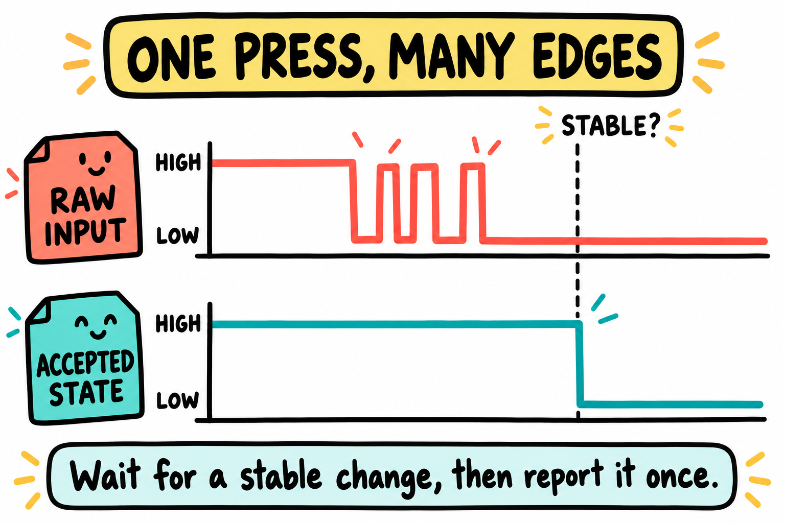
One physical press can produce several electrical edges. Our filter qualifies observed samples before reporting one change. The drawing has no time scale and does not prove the level stayed constant between samples.
Contact bounce adds short transitions around a real change. Two matching samples separated by 20 ms do not prove that the signal stayed steady between them. They are a cheap filter, useful when blocking the caller is acceptable:
int key_read_debounced(void)
{
    int first = (GPIO_PSR(GPIO1_BASE) & KEY_BIT) == 0u;
    mdelay(20);
    int second = (GPIO_PSR(GPIO1_BASE) & KEY_BIT) == 0u;
    return first == second ? second : -1;
}
Here -1 means the samples disagree, not a diagnosis of the physical cause. Returning 1 is a level report; repeatedly calling it while the key is held still returns 1. The next driver turns qualified level changes into events without delaying inside the sampling function.
A consecutive-sample filter
Create bsp/key/bsp_key.h:
#ifndef BSP_KEY_H
#define BSP_KEY_H

typedef enum {
    KEY_NONE,
    KEY_PRESS,
    KEY_RELEASE
} key_event_t;

void key_init(void);
key_event_t key_tick(void);    /* One call per real 10 ms sample. */

#endif
Create bsp/key/bsp_key.c:
#include <stdint.h>
#include "bsp_key.h"
#include "imx6ull.h"

static uint8_t history;
static unsigned down;

void key_init(void)
{
    REG(CCM_CCGR1) |= CCGR_GPIO1_GATE;
    REG(CCM_CCGR4) |= (3u << 2);    /* IOMUXC interface gate. */
    GPIO_GDIR(GPIO1_BASE) &= ~KEY_BIT;
    REG(KEY_PAD) = (1u << 16);     /* Hysteresis; external R12 supplies pull-up. */
    REG(KEY_MUX) = 5u;
    history = 0u;
    down = 0u;
}

key_event_t key_tick(void)
{
    unsigned raw = (GPIO_PSR(GPIO1_BASE) & KEY_BIT) == 0u;
    history = (uint8_t)((history << 1) | raw);
    if (history == 0xFFu && down == 0u) {
        down = 1u;
        return KEY_PRESS;
    }
    if (history == 0u && down != 0u) {
        down = 0u;
        return KEY_RELEASE;
    }
    return KEY_NONE;
}
Eight consecutive down samples produce one press; further down samples produce none until eight up samples qualify a release. With a 10 ms cadence, the decision arrives roughly 70-80 ms after a steady transition, depending on its position between samples. A key held at startup is treated as a new press after qualification. Hysteresis improves input threshold behavior but does not remove mechanical bounce.
This is a shift-register filter, not an up/down integrator. Its window is a
starting choice to measure on your switch, not a universal safe minimum.
Short taps may be rejected. If you move key_tick() into an EPIT interrupt
service routine, queue its events for foreground consumption: do not call
printf or a blocking beep from the ISR. A shared queue needs explicit
producer/consumer and overflow rules; volatile alone does not supply them.
Hardware and software alternatives
Hardware filtering is an alternative, not automatically the best design. An RC network with a suitable Schmitt input can suppress contact chatter, but its thresholds and time constants need calculation. The supplied MINI KEY0 circuit has a pull-up and switch, not a separate RC/Schmitt filter. GPIO interrupts can also be combined with software debounce. Later, Chapter 45’s Linux gpio-keys driver presents qualified changes to the input subsystem; it does not make the board’s electrical design irrelevant.
18B.3 Buzzer, a square wave on GPIO5_IO01 (active-low via PNP)
First make the output safely idle, independently of the buzzer type. Create
bsp/beep/bsp_beep.h:
#ifndef BSP_BEEP_H
#define BSP_BEEP_H
#include <stdint.h>

void beep_init(void);
void beep_set(unsigned on);    /* Active buzzer: on/off control. */
int beep_tone(uint32_t hz, uint32_t ms); /* Verified passive load only. */

#endif
Create bsp/beep/bsp_beep.c:
#include "bsp_beep.h"
#include "bsp_delay.h"
#include "imx6ull.h"

void beep_init(void)
{
    REG(CCM_CCGR1) |= CCGR_GPIO5_GATE;
    GPIO_DR(GPIO5_BASE) |= BEEP_BIT;    /* Preload OFF before enabling output. */
    GPIO_GDIR(GPIO5_BASE) |= BEEP_BIT;
    REG(BEEP_PAD) = 0xB0u;             /* Push-pull, DSE=6, slow slew; no pull. */
    REG(BEEP_MUX) = 5u;
}

void beep_set(unsigned on)
{
    if (on != 0u)
        GPIO_DR(GPIO5_BASE) &= ~BEEP_BIT;
    else
        GPIO_DR(GPIO5_BASE) |= BEEP_BIT;
}

int beep_tone(uint32_t hz, uint32_t ms)
{
    beep_set(0u);
    /* Input limits bound the multiplication and reject division by zero. */
    if (hz < 200u || hz > 5000u || ms == 0u || ms > 1000u)
        return -1;

    uint32_t half_us = 500000u / hz;
    uint32_t cycles = hz * ms / 1000u;
    for (uint32_t i = 0u; i < cycles; ++i) {
        beep_set(1u);
        udelay(half_us);
        beep_set(0u);
        udelay(half_us);
    }
    beep_set(0u);
    return 0;
}
The initial DR write avoids enabling an output with its old latch value low.
It does not guarantee a silent power-up before firmware runs; that also
depends on the fitted circuit and pad reset state. The SNVS pad’s SPEED
field is read-only in the RM. 0xB0 selects the writable output settings;
do not interpret it as a promised current rating.
For a verified passive load, beep_tone(1000, 200) requests approximately
200 cycles at 1 kHz. Integer rounding, GPIO access time, interrupt latency,
and the GPT clock affect the waveform and duration. A 1 us timer tick is
resolution, not a guarantee of 1 us waveform accuracy. Measure the output
with suitable equipment before treating pitch or duty cycle as calibrated.
Only this foreground driver should modify GPIO5’s output latch in the example:
read/modify/write operations can lose a concurrent writer’s update.
Why not only a GPIO toggle in a tight loop?
The delay-based loop still occupies the CPU for the whole note. A hardware timer or PWM can generate a waveform while the application does other work, but only if its output can reach the load. RM 32.5.4 lists GPIO5_IO01, not a PWM alternate function, for SNVS_TAMPER1. Chapter 48’s PWM framework cannot reroute the reference BEEP wire by software. A hardware PWM design needs a separately verified PWM-capable pad and load connection. Keep that as a different hardware setup, not a promised replacement on this net.
18B.4 Putting it together
Use the refactored clock audit, UART/mini-printf, and GPT/delay code from
your earlier project. Declare them in their BSP headers;
retain Chapter 16’s int gpt_init(uint32_t ipg_hz) contract and the
free-running 1 MHz gpt_now_us(). Check initialization before either delay
function is used. Keep the approved ROM/board clock tree, not an assumed
frequency or an unqualified clock-switching routine. Chapter 18A’s
Makefile discovers the two new driver folders automatically.
LED0 driver
Chapter 10 initialized LED0 directly in main. Move that same board-specific
sequence into bsp/gpio/bsp_gpio.c, with its declaration in
bsp/gpio/bsp_gpio.h. This supplies the led_init() used below rather than
assuming an earlier driver already exists.
bsp/gpio/bsp_gpio.h:
#ifndef BSP_GPIO_H
#define BSP_GPIO_H

void led_init(void);

#endif
bsp/gpio/bsp_gpio.c:
#include "bsp_gpio.h"
#include "imx6ull.h"

void led_init(void)
{
    REG(CCM_CCGR1) |= CCGR_GPIO1_GATE;
    REG(LED_MUX) = 5u;
    REG(LED_PAD) = 0x17059u;
    GPIO_DR(GPIO1_BASE) |= LED_BIT;      /* Preload active-low LED OFF. */
    GPIO_GDIR(GPIO1_BASE) |= LED_BIT;
}
The clock, mux, pad, OFF-latch, and output-direction order matches Chapter 10. Keep its reference board and fresh-ROM prerequisites; the pad setting is not a generic value for other loads or boards. Only the GPIO1 bit-3 latch/direction changes here, leaving KEY0’s bit-18 input configuration intact.
Application
This first integration uses no EPIT callback, GIC setup, or wfi: sampling
and event handling share the foreground loop. For the later interrupt
version, Chapter 16’s epit_init(ipg_hz) takes a clock rate, not a sampling
period; count ten of its 1 ms ticks between key samples.
Leave IRQ/FIQ masked for this polled example. printf below means the earlier
bare-metal implementation, not an automatically linked libc.
#include "bsp_clk.h"
#include "bsp_gpio.h"
#include "bsp_uart.h"
#include "bsp_gpt.h"
#include "bsp_delay.h"
#include "bsp_key.h"
#include "bsp_beep.h"
#include "imx6ull.h"

int printf(const char *fmt, ...);

int main(void)
{
    clk_enable_lab_gates();
    uart_init();
    uint32_t ipg_hz = clocks_get_ipg_hz();
    if (gpt_init(ipg_hz) != 0) {
        printf("GPT setup failed; IPG=%u Hz\r\n", (unsigned)ipg_hz);
        for (;;) { }
    }
    led_init();
    key_init();
    beep_init();

    printf("Button input ready.\r\n");
    uint32_t sampled = gpt_now_us();
    for (;;) {
        uint32_t now = gpt_now_us();
        if ((uint32_t)(now - sampled) < 10000u)
            continue;
        sampled = now;              /* Do not invent catch-up samples. */
        key_event_t event = key_tick();
        if (event == KEY_PRESS) {
            GPIO_DR(GPIO1_BASE) ^= LED_BIT;
            printf("press\r\n");
        } else if (event == KEY_RELEASE) {
            printf("release\r\n");
        }
    }
}
A startup-sound variant keeps sound before the initial sampled value.
For an identified active buzzer, the envelope is
beep_set(1u); mdelay(100); beep_set(0u);. For a verified passive load,
beep_tone(2000u, 100u) requests a tone and can report failure. A tone inside
the polling loop pauses button sampling. Interrupt sampling with a foreground
event queue separates those responsibilities when that pause is unacceptable.
The application’s intended behavior is that a qualified press toggles LED0 and prints press; holding it does not repeat the event; a qualified release prints release. A build alone does not establish those observations.
18B.5 Key Notes
A pad level and an application event are different interfaces. PSR reports the input now. The history filter reports one qualified press or release rather than repeating while a level is held.
Eight matching samples at a real 10 ms cadence qualify the transition. Sparse sampling can miss bounce and short taps, while immediate catch-up calls create no new observations. Hysteresis does not remove mechanical chatter.
Board connector numbers and circuit polarity govern the driver. MINI KEY0 uses UART1_CTS/GPIO1_IO18, while BEEP is an active-low PNP-switched load on GPIO5_IO01. A shared alias or SoC controller name does not establish the route.
The fitted buzzer type determines whether an on/off envelope or a driven waveform is appropriate. Timer resolution, GPIO overhead and interrupt latency limit software-tone accuracy. The reference BEEP pad has no PWM route to select.
Blocking sound delays foreground sampling. An interrupt-based alternative needs a bounded event queue, producer/consumer rules and overflow handling, with UART and sound outside the ISR. GPIO read-modify-write also needs one writer or protected updates.
Gesture timing, such as a double tap, needs defined endpoints between qualified events and wrap-safe elapsed comparisons. Missed samples cannot be reconstructed from the number of elapsed timer ticks.
An idle design needs a race-aware event check and a working wake source. Whole-board current includes regulators, peripherals and LEDs, not just the CPU. Do not change meter wiring on a powered board.
18B.6 Pitfalls
Wrong key route. MINI V2.2’s onboard KEY0 is GPIO1 bit 18. The core’s
KEY0alias on pin 49 names a different baseboard signal here; follow both connector drawings.Wrong SNVS pad offsets. BEEP uses
0x0229000Cand0x02290050, not offsets 0 and 0x18. A plausible-looking wrong address can change another pad.Reading a latch instead of a pad. Use PSR for this input. Check GDIR is input and UART1_CTS is muxed to GPIO1_IO18 before tuning debounce.
Noisy or floating level. Check R12 and the fitted circuit with power off; a steady read alone is not proof that the pull-up is correctly fitted. Do not substitute a new pull configuration without considering other owners of the pad.
Calling every loop iteration a tick. The history window counts samples, not milliseconds. Late foreground work stretches the window; repeated immediate catch-up calls falsely claim extra observations.
Unexpected sound. Check buzzer type, polarity, idle-high initialization, clock gates, and GPT setup. Do not assume an oscillator-equipped buzzer will play requested notes.
Shared GPIO writes. A foreground read/modify/write can overwrite an ISR’s change to another bit of the same bank. Give the bank one writer or protect the update deliberately.
18B.7 Going deeper
Supplied MINI v2.2 schematic, sheet 2, and CORE schematic, sheets 6 and 8: transistor circuit, package pad, and connector route.
IMX6ULLRM Rev. 1, Chapters 28 and 32: GPIO PSR/GDIR and the exact mux/pad fields, including the tamper-pad qualification.
Pinned UART1_CTS pin-function definition: offset
0x008Cfor mux,0x0318for pad, ALT5 for GPIO1_IO18. Add the main IOMUXC base0x020E0000to obtain the addresses used here.Jack Ganssle, A Guide to Debouncing: measured contact behavior and filter design. Use measurements to choose a window rather than adopting one value for every switch.
Linux drivers/input/keyboard/gpio_keys.c: the event/debounce path we meet in Chapter 45. drivers/pwm/pwm-imx27.c illustrates the PWM controller, not proof of a PWM route to BEEP.
Next chapter: Chapter 18C: Bare-metal RTC. Separate a retained counter from the main-powered interface that lets the CPU read it.