Chapter 4: ARMv7-A and the Cortex-A7, for the MCU engineer
An interrupt handler can return to the right instruction and still break the program it interrupted. If it overwrote a register without preserving the old value, returning to the right address does not recover that lost value.
On Cortex-M, hardware saves a useful part of that context before your handler begins. Our Cortex-A7 does not make the same stack push. It selects some different registers on exception entry and leaves software to preserve the rest. Familiar-looking C and assembly therefore sit on top of a different arrangement. We need to know what the core did before our first handler instruction, and what it expects us to do afterward.
Follow the integer registers, SVC and IRQ modes, banked SP/LR, and physical versus virtual addresses on a first reading. They explain the early startup and exception work. Caches, timers, security, and virtualization have their own later uses; their tables can remain reference material until the corresponding design appears.
4.1 Where the Cortex-A7 sits in the ARM lineup
Cortex-A7, Cortex-M7: the matching number invites an assumption that the cores are close relatives with similar software requirements. The letter matters more here. Arm names describe two different things:
Profile letter.
Afor “Application” (smartphones, set-top boxes, embedded Linux),Rfor “Real-time” (storage controllers, automotive),Mfor “Microcontroller” (the Cortex-M0/M3/M4/M7/M33 you have worked with).Architecture version. v6, v7, v8, v9. The version determines the instruction set and which features are present. The core implementation determines pipeline depth, cache topology, and clock ceiling.
Our i.MX6ULL has one Cortex-A7, using the ARMv7-A architecture. It includes the VFPv4 floating-point unit and NEON vector instructions, but no Cortex-M companion. Some other i.MX6 parts, such as SoloX, include an M4; do not infer the contents of this chip from that family name.
The core name also does not specify the board’s clock frequency. Clock limits come from the fitted silicon’s speed grade and electrical conditions. The supplied industrial datasheet lists 528 and 792 MHz grades, while Linux v6.6’s ULL device tree lists operating points to be constrained by the part and board. A later example selects 696 MHz, but that is not a universal reset, BSP, or Linux frequency. Chapter 5 shows how to read the part marking before choosing a clock setting.
The Cortex-A7 is an in-order, dual-issue core with an 8-stage pipeline. We do not need to study the pipeline to write the first program. Its register and exception model, however, gives us a manageable place to learn the ARMv7-A mechanisms later used by U-Boot and Linux.
4.2 Comparing the Cortex-M and Cortex-A7 models
Use the following table to place familiar MCU features beside the Cortex-A7 equivalents. It is a comparison, not a specification for every Cortex-M part:
Feature |
Cortex-M (typical) |
Cortex-A7 |
|---|---|---|
Address space |
Single, flat, physical |
Virtual, per-context, via MMU |
MMU |
No (some have MPU) |
Short-descriptor tables for our examples; LPAE also supported |
Privilege levels |
Privileged / Unprivileged |
PL0/PL1, plus PL2 for HYP; modes below |
Banked registers |
A few (MSP, PSP) |
Selected registers are banked in exception modes |
Caches |
L1 I/D on M7+, sometimes none |
L1 I/D mandatory. L2 is integrated inside the Cortex-A7 MPCore platform (128 KB on i.MX6ULL), with no separate PL310 controller |
TLB (Translation Lookaside Buffer, the MMU’s address-translation cache) |
No |
Yes |
Generic timer |
No (SysTick) |
Yes, architected |
Interrupt controller |
NVIC (in-core, vectored) |
GIC, an external Generic Interrupt Controller block. Prioritized, not auto-vectored |
Exception model |
Tail-chained, automatic stacking |
Mode switch, software-saved context |
FPU |
Optional VFP variant |
VFPv4 (mandatory in i.MX6ULL) |
SIMD |
DSP extensions (limited) |
NEON (64-/128-bit) |
Atomic ops |
Exclusives on M3/M4/M7; not M0/M0+ |
LDREX/STREX |
Instruction set |
Thumb; M0/M0+ have a smaller subset than M3/M4/M7 |
ARM and Thumb-2 for this book |
Start with the exception-model row. It explains how the opening handler could return correctly yet leave the program damaged. Then look at the MMU row, which explains Chapter 2’s separate process mappings. These are changes to how software uses the machine, not just extra peripherals in a longer feature list. Timer and NEON support are useful later, but their presence does not mean every Linux configuration uses them.
4.3 Exception modes and banked registers
Think of the first line in a Cortex-M C interrupt handler. It looks like an ordinary function, but the processor has already done some of the work that function relies on:
On Cortex-M, the usual sequence is:
Hardware automatically saves R0-R3, R12, LR, PC, and xPSR to the current stack.
Hardware loads PC from the vector table.
Your ISR runs.
BX LR(with the special EXC_RETURN value in LR) tells the CPU to unstack and resume.
There is also a difference in the vector itself. A Cortex-M exception vector contains a handler address. In the ARM-state vector table we will use on Cortex-A7, each slot contains an instruction, commonly a branch or a load into pc. The CPU starts executing that slot; it does not treat it as a Cortex-M handler pointer. See the Arm Cortex-A Programmer’s Guide, Section 11.1.3.
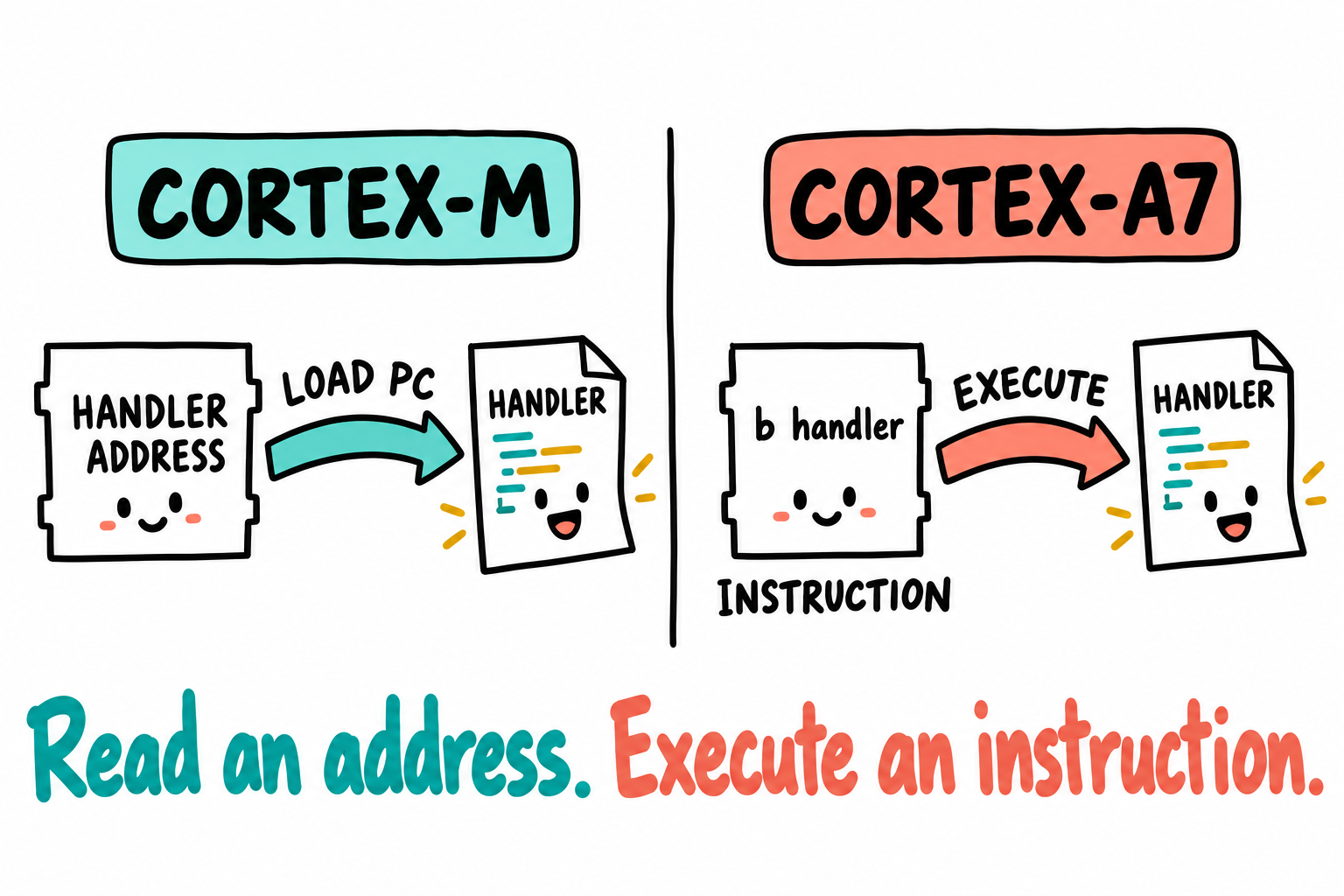
An address tells the core where to go. A branch is an instruction it executes to get there. This sketch compares handler-vector entries. The Cortex-M table’s first word is a separate case: it supplies the initial stack pointer. b handler is an example, not a complete vector table or interrupt handler.
Our Cortex-A7 does not do that automatic stack push. Instead, an exception changes the processor mode and selects the register view for that mode. Some register names now refer to different physical registers. These separate copies are called banked registers.
Watch sp when an IRQ interrupts SVC code. Before the interrupt it refers to sp_svc; afterward the same name refers to sp_irq. The old stack pointer was not pushed anywhere. Its physical register is still there, out of the handler’s current view. The IRQ stack must already have been initialized. Now watch r0: it has no corresponding IRQ bank. If the handler uses it, the interrupted value must be saved and restored by software.
The tables below describe this Cortex-A7’s nine modes. Other A-profile cores need not implement exactly the same set. First use the tables to follow SVC and IRQ; the extra security and hypervisor modes can wait.
Before reading every row, hold the value 5 in r0 and imagine an IRQ interrupting SVC code. The CPU saves status in SPSR_irq, records an exception link in lr_irq, selects sp_irq, and enters the IRQ vector. It does not create an IRQ copy of r0. A handler that overwrites the 5 must save it and restore it before returning.
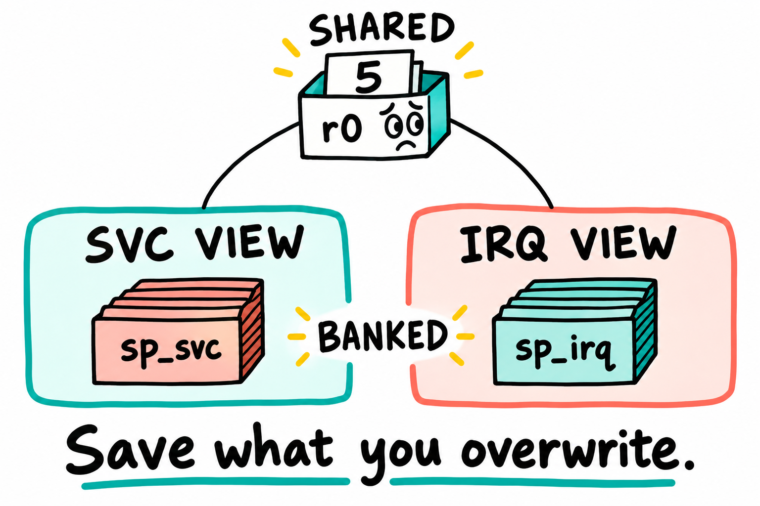
Two SP registers, but one shared r0. The paper piles represent the stacks selected by those pointers. BANKED refers to the SP registers, not the stack memory. The connecting lines show that sharing, not a copy operation. IRQ entry pushes nothing automatically.
There is one LR/SPSR bank per exception mode, not a fresh frame for each interrupt. Preserve the return state before a C call overwrites LR or nesting can re-enter that mode. Ordinary IRQ entry masks IRQ; enabling nesting requires deliberate save/restore work. Reset is not a returnable saved pre-reset context. Chapter 15 implements the full entry and return path.
The registers you are looking at
Ordinary integer instructions use r0 through r15. Several have familiar aliases: sp for the stack pointer, lr for the link register, and pc for the program counter. CPSR records the current status and mode; an exception mode also has an SPSR for saved status. The table connects these names to their roles in C calls and exception handling:
Register |
Common alias |
What it does |
Beginner note |
|---|---|---|---|
|
argument / result registers |
Initial core argument/result registers under AAPCS32; four ordinary 32-bit integer/pointer arguments fit here. Wider or aligned values follow the ABI’s allocation rules. |
Exception handlers must preserve interrupted values they overwrite, including through a C call. |
|
general saved registers |
General-purpose registers that C functions normally preserve for their caller. |
|
|
platform register |
ABI-defined register. Some systems use it for a static base, thread pointer, or other platform role. |
Treat it as “do not assume” in hand-written assembly that calls C. |
|
|
General saved register. Some older ABIs used it as a stack limit. |
Usually another callee-saved register in Linux code. |
|
|
Frame pointer when frame pointers are enabled. |
Useful when reading backtraces or compiler-generated assembly. |
|
|
Scratch register used during function calls. Linker-generated branch stubs may use it. |
Caller-saved. Do not expect it to survive a function call. FIQ also has |
|
|
Stack pointer. Points at the current mode’s stack. |
Banked in exception modes, so |
|
|
Link register. Holds a subroutine return address, or an exception return address after an exception. |
Banked in most exception modes, so |
|
|
Program counter, the address of the instruction stream. |
Writing to |
|
current status |
Holds condition flags, interrupt masks, Thumb/ARM state, and current processor mode. |
The CPU changes CPSR when it enters an exception. |
|
saved status |
Snapshot of CPSR taken when an exception entered that mode. |
Used on exception return to restore the old mode, flags, and interrupt-mask state. User/System mode do not have an SPSR. |
|
hypervisor exception link |
Return address used by HYP mode. |
HYP is special: it uses |
Knowing what a register does is one question. Knowing which physical copy is visible is another. The next two tables separate those questions by putting modes in columns and register names in rows.
First, the Cortex-M view:
Register |
Thread mode |
Handler mode |
|---|---|---|
|
Same physical registers. |
Same physical registers, exception entry stacks |
|
|
|
|
Normal function return address. |
|
|
Current instruction stream. |
Handler instruction stream loaded from the vector table. |
status |
Active |
Active |
Here the general-purpose registers are shared. Hardware saves the listed interrupted values on entry and restores them on exception return. Thread mode may use MSP or PSP, while Handler mode uses MSP.
Now the Cortex-A7 view:
Register |
USR |
SYS |
FIQ |
IRQ |
SVC |
ABT |
UND |
MON |
HYP |
|---|---|---|---|---|---|---|---|---|---|
|
shared |
shared |
shared |
shared |
shared |
shared |
shared |
shared |
shared |
|
shared |
shared |
|
shared |
shared |
shared |
shared |
shared |
shared |
|
|
|
|
|
|
|
|
|
|
|
|
|
|
|
|
|
|
|
|
|
shared |
shared |
shared |
shared |
shared |
shared |
shared |
shared |
shared |
|
shared |
shared |
shared |
shared |
shared |
shared |
shared |
shared |
shared |
|
none |
none |
|
|
|
|
|
|
|
HYP return address |
none |
none |
none |
none |
none |
none |
none |
none |
|
shared means the same physical register is visible in that mode. For r8-r12, FIQ uses its own banked copies while the other modes share the ordinary registers. A suffix such as _irq means that mode has its own banked physical register. HYP mode shares lr_usr and uses ELR_hyp for exception return, as marked by * in the table.
The nine modes
Mode |
Abbreviation |
Entered on |
Banked regs |
|
|---|---|---|---|---|
User |
USR |
(normal program execution) |
none |
|
FIQ |
FIQ |
Fast interrupt |
R8-R12, R13, R14, SPSR |
|
IRQ |
IRQ |
Normal interrupt |
R13, R14, SPSR |
|
Supervisor |
SVC |
Reset, |
R13, R14, SPSR |
|
Monitor |
MON |
Secure Monitor Call ( |
R13, R14, SPSR |
|
Abort |
ABT |
Memory/prefetch abort |
R13, R14, SPSR |
|
Hyp |
HYP |
Hypervisor (virtualization) |
R13, ELR_hyp, SPSR |
|
Undefined |
UND |
Undefined instruction |
R13, R14, SPSR |
|
System |
SYS |
Privileged mode using the user register view |
none |
|
The mode bits live in CPSR.M[4:0]. A returnable exception saves status in the destination mode’s SPSR. Reset does not supply a restorable pre-reset frame. For C/assembly interfaces, consult AAPCS32’s parameter-passing rules, not a one-register-per-C-argument assumption.
MON serves security-state transitions, and HYP serves virtualization. This Cortex-A7 supports those extensions, but our first bring-up path does not use them. Keep USR, SVC, IRQ, ABT, and UND in view first. Part IX returns to HYP.
Total physical register count exposed by Cortex-A7: 34 general-purpose, 8 status (CPSR + 7×SPSR), plus ELR_hyp. That is 43 registers. A normal non-HYP mode sees at most 18 at once: r0-r15, CPSR, and its SPSR. HYP sees ELR_hyp as its extra exception-return address.
The opening puzzle now has a precise cause: banking preserves selected exception state, not every value the handler might overwrite. HYP has its own return arrangement using ELR_hyp; it is not the PL1 IRQ return described below.
What this means in practice
Put the two worlds side by side:
Moment |
Cortex-M |
Cortex-A / ARMv7-A |
|---|---|---|
Interrupt accepted |
Hardware picks the vector and starts exception entry. |
Hardware switches to IRQ mode and branches through the exception vector. |
Registers saved automatically |
|
Nothing is pushed. |
Hardware entry-frame stack |
The interrupted context’s active MSP or PSP. |
No hardware stack frame is pushed. |
SP used by handler instructions |
MSP. |
Initially the banked |
What |
A special |
The banked |
Handler prologue |
Often no assembly is needed, a C ISR can start immediately. |
Assembly must save enough state before calling C. |
Return |
|
Software restores saved registers, then uses an appropriate exception-return instruction to restore CPSR and PC together. |
For an ordinary PL1 IRQ with the original IRQ link restored, subs pc, lr, #4 is one return form: it adjusts the IRQ link and restores status from SPSR_irq with the return PC. This is not a complete handler. SVC, abort, and HYP returns have different rules; an ordinary BX LR is not an A-profile EXC_RETURN operation. Do not restore CPSR first and then branch as two independent steps. Linux’s entry-armv.S contains its entry/exit machinery.
PL0 vs PL1 vs PL2
Across the nine modes, ARM defines three privilege levels:
PL0 (unprivileged, like Cortex-M unprivileged Thread mode): only USR mode. This is the mode applications run in.
PL1 (privileged): most modes, including SVC, IRQ, FIQ, ABT, UND, and SYS. This is the level the kernel runs at.
PL2 (hypervisor): only HYP mode. It can intercept selected PL1 operations and transfer control to the hypervisor.
ARM TrustZone adds a separate Security state: Normal World or Secure World, with restricted combinations. On ARMv7-A, MON exists only in Secure state and HYP/PL2 only in Non-secure state; most other modes can exist in either. MON handles transitions between the worlds. Security state is not another privilege-level number.
MMU/control and cache-maintenance operations generally require privileged execution. Some CP15 registers, such as user thread-ID registers, are user-accessible; access rights are defined per register.
You will also meet the name CP15 in startup assembly. It is the ARMv7-A access path for system-control registers, not another chip on the board. Instructions such as mrc and mcr access controls including the MMU enable bits in SCTLR, page-table bases in TTBR0 and TTBR1, and the exception-vector base in VBAR. Cache maintenance and generic-timer access also use this path. AArch64 uses named system-register instructions instead.
Linux runs ordinary user instructions in USR/PL0 and uses PL1 modes for kernel execution. Much kernel code runs in SVC mode; exception entry can use IRQ or another mode before an entry veneer changes it. A syscall or interrupt can trigger the hardware transition. Do not equate every kernel instruction with the first mode selected by its exception vector.
HYP mode is the extra layer used by a hypervisor. A guest kernel runs as if it controls PL1, but sensitive actions can be redirected to PL2. The hypervisor can then decide whether to allow the action, emulate it, or stop the guest. The matching instruction is hvc (Hypervisor Call), similar to svc but for calls into the hypervisor.
Do not confuse HYP mode with Monitor mode:
HYP / PL2: virtualizes Normal World operating systems.
MON / Monitor mode: switches between Secure World and Normal World for TrustZone.
Part IX uses this distinction in its Xen design: HYP mode controls guests, while OP-TEE in Chapter 124 uses Monitor/Secure-world mechanisms.
Chapter 2’s syscall now has a more concrete explanation. Its svc instruction triggers a Supervisor Call exception from USR to SVC mode. SP and LR select their SVC copies, and the kernel handler runs with privileged access. The application requested this transition deliberately, but the core still enters an exception. The mode table describes something we have already seen from the caller’s side.
4.4 The CPSR / SPSR program status registers
CPSR (Current Program Status Register) is the A-profile equivalent of M-profile’s xPSR, but more is in it:
 Selected fields only:
 31 30 29 28 27 ...  9  8  7  6  5  4  3  2  1  0
 N  Z  C  V  Q       E  A  I  F  T  M4 M3 M2 M1 M0
N, Z, C, V: condition flags (the same as M-profile: negative, zero, carry, overflow)
Q: saturation flag, set by saturating arithmetic instructions
IT[7:0] (split bits 26:25 + 15:10): IF-THEN block state for Thumb-2 conditional execution
J (bit 24), T (bit 5): our examples use ARM (
J=0,T=0) or Thumb (J=0,T=1). Other architectural encodings include legacy ThumbEE/Jazelle. Cortex-A7’s Jazelle implementation is trivial, not Java-bytecode acceleration; those encodings are not additional instruction sets used by this book.GE[3:0] (bits 19:16): flags used by packed integer instructions such as
UADD8, not NEON comparisons.E: current data-endianness state where applicable, not a choice attached to each load/store. This book uses little-endian data.
A: asynchronous abort mask
I: IRQ mask (
I=1disables IRQs)F: FIQ mask
T: Thumb state (
T=1means executing in Thumb)M[4:0]: current processor mode (encoding for USR/SVC/IRQ/…)
For a returnable exception, the CPU saves CPSR in SPSR_<mode> and selects the exception mode. That bank can be overwritten by another entry to the same mode. The handler can read saved status with mrs Rn, spsr; privileged cps instructions can change the current mode and interrupt masks. None makes reset a saved frame to return to.
In the early startup examples, the mode field and I/F interrupt masks describe which register bank is active and whether IRQ or FIQ may interrupt the code. The remaining status fields become useful when reading instruction behavior and more advanced exception paths.
4.5 Memory model and the MMU
Recall the two processes in Chapter 2 that used the same pointer value for different physical RAM. The CPU needs a way to decide which translation applies. On our non-virtualized path, stage 1 performs that virtual-to-physical translation using tables in memory. Here we can identify the structures that make the earlier example possible.
The Cortex-A7 also supports a second translation stage for virtualization. Do not confuse a translation stage with a table level: two stages are guest and hypervisor translations, while two levels are successive table lookups within one translation. The initial bare-metal design needs only stage 1.
Translation table formats
ARMv7-A supports two translation table formats:
Short descriptor. Our ordinary mappings use this SoC’s 32-bit physical map. Small pages use two table levels; a section can finish at Level 1. The architecture also defines extended supersection cases outside this example’s scope.
Long descriptor (LPAE, 40-bit physical, 3-level tables). Used when a system needs larger physical addresses or LPAE features. Our board has at most 512 MiB of DRAM, so this book does not need LPAE.
Here are two distinct short-descriptor paths, using a full, unsplit L1 table (TTBCR.N=0):
4 KiB small page:
  VA[31:20] -> L1 entry -> L2 table indexed by VA[19:12]
                         -> physical page base + VA[11:0]

1 MiB section:
  VA[31:20] -> L1 section entry
                         -> physical section base + VA[19:0]
For illustrative VA 0x12345678, the small-page indices are 0x123 and 0x45, with offset 0x678. A section uses the same L1 index but offset 0x45678, with no L2 lookup. A full L1 table has 4096 entries/16 KiB; a coarse L2 table has 256 entries/1 KiB. Other table-split settings change the applicable indexing rules.
Each Level-1 entry can:
Point to a Level-2 table (resolves a 1 MB region in 4 KB pages).
Be a 1 MB “section” directly (no Level-2 lookup needed, saving a memory access).
Be a 16 MB “supersection” (less common).
The first lookup need not send the MMU to a second table: a section entry can describe the region directly. That is why the descriptor’s type matters before its other fields. Section and small-page mappings also differ. For now, ask what a completed mapping must tell the MMU: the physical address, who may access it, and how accesses to that memory should behave.
The corresponding leaf fields include access permissions (AP), execute-never (XN), and memory attributes (TEX/C/B and shareability). Relevant L1 descriptors also select a domain; a domain in “client” mode applies the mapping’s permissions. Chapter 17 decodes the exact section format used by its example.
The TLB caches recent address translations. There is also an ASID (Address Space ID, 8 bits) that tags TLB entries so context switches do not need a full TLB flush.
Chapter 17 follows a minimal L1-only page table, separating descriptor layout, memory attributes, and the control-register sequence that activates translation.
What the kernel does with this
Linux on ARMv7-A:
In the v6.6 non-LPAE two-level path, uses unsplit tables and switches the process table through TTBR0. Other configurations can select TTBR0/TTBR1 regions; a virtual-address user/kernel split does not imply that hardware-register split. See proc-v7-2level.S.
Splits the 4 GB virtual address space into a user range (
0x00000000-0xBFFFFFFF) and kernel range (0xC0000000-0xFFFFFFFF) by default.CONFIG_PAGE_OFFSETcontrols this split.Uses a fixed offset for the linear mapping of low RAM (
PHYS_OFFSETtoPAGE_OFFSET), not arbitraryvmalloc,ioremap, or high-memory pointers. Drivers use mapping and DMA APIs, not subtraction from any kernel pointer. See the ARM memory layout.
With that default split, the user range occupies about 3 GiB of virtual address space. This is a layout choice, not a statement that each process has 3 GiB of physical RAM.
4.6 Caches
The CPU writes a new value to a buffer. Has that value reached the memory a peripheral will read? With a write-back cached mapping, the modified bytes can still be in the CPU’s cache. A cache makes repeated accesses faster by keeping copies nearby, but low-level code must also know when those copies agree with memory. First distinguish the i.MX6ULL’s two L1 caches:
Cache |
Size |
Ways |
Line size |
Organization |
|---|---|---|---|---|
L1 instruction |
32 KiB |
2 |
32 bytes |
VIPT: virtually indexed, physically tagged |
L1 data |
32 KiB |
4 |
64 bytes |
PIPT: physically indexed, physically tagged |
These properties are specified separately in the Cortex-A7 TRM DDI 0464F, Chapter 6. NXP RM Chapter 12 specifies the implemented sizes and integrated 128 KiB unified L2. This SoC does not have the separate PL310 controller used by some earlier i.MX6 parts.
Two A-profile cache properties are important here:
Processor reset is not our image’s entry state. Caches are disabled at architectural reset, but the Boot ROM runs before
_startand can enable L1 instruction caching while loading [RM 8.4.4]. Startup must account for the documented ROM handoff contract and normalize the state its design requires. Do not infer “all caches off” merely from having cold-started the board. Chapter 6’s skeleton is build-only, not a complete handoff implementation.I/D geometry differs. Do not use one line size for both maintenance loops. DMA sharing and changed executable instructions require operation-specific coherency work in Chapters 17 and 51.
The maintenance names describe different actions. Clean writes modified, or dirty, data toward the point required for the other observer to see it. Invalidate discards a cached copy so it will not be reused. Discarding dirty data without first cleaning it can lose writes. Clean and invalidate performs both actions; “flush” alone does not specify which.
The encodings below are maintenance reference, not a complete procedure to run. Chapter 17 supplies the required ranges, attributes, synchronization, and coherency-point definitions; Linux drivers use the appropriate DMA APIs.
ARMv7-A performs cache maintenance through CP15 operations. The assembly uses mcr with an operation-specific CP15 encoding:
Operation |
ARMv7-A form |
Architectural name |
|---|---|---|
Invalidate D-cache line by virtual address |
|
|
Clean D-cache line by virtual address |
|
|
Clean and invalidate D-cache line by virtual address |
|
|
Invalidate all instruction caches to PoU |
|
|
Set/way operations are also available for whole-cache maintenance during early boot.
Chapter 17 explains a small cache-maintenance primitive. Linux’s arch/arm/mm/cache-v7.S provides the operating system’s broader implementation.
4.7 The generic timer
The familiar SysTick combines a counter with an interrupt mechanism. The ARMv7 generic timer separates these ideas: a shared system counter supplies time, while per-CPU comparators decide when to raise an interrupt. Cortex-A7 supports this interface, but the SoC’s clocks and power integration still determine when it operates.
Key registers (CP15 access):
CNTFRQ: counter frequency (Hz). Software writes this once at boot to inform the rest of the system.CNTPCT: current counter value (64-bit physical counter).CNTP_CVAL: comparator value. The timer fires when CNTPCT >= CNTP_CVAL.CNTP_CTL: enable + interrupt mask + status.
Linux’s arch_timer supports it, but v6.6 imx6ul.dtsi disables the generic timer, and imx6ull.dtsi does not enable it. The inherited setup uses SoC timer facilities such as GPT; do not enable a node merely because the core implements its architecture. Chapter 16 uses GPT/EPIT on bare metal. After Linux boots, inspect timer/clocksource messages and /sys/devices/system/clocksource/clocksource0/current_clocksource to identify the actual configuration.
Keep that separation in mind when reading the register names: SysTick is a per-core 24-bit down-counter, while the generic timer uses a shared 64-bit counter and per-CPU comparator state. Reading the time and arranging a future interrupt are related operations, but not the same one.
4.8 The Generic Interrupt Controller (GIC)
The Cortex-M NVIC was inside the core. The A-profile equivalent, the GIC, is outside the core. The i.MX6ULL integrates a GIC-400 (an implementation of GIC v2).
We know how IRQ entry changes the CPU state. One question is still unanswered: which peripheral caused it? The GIC supplies that part of the interrupt path. It splits the work between a system-wide distributor and a CPU interface:
GICv2 has two parts:
Distributor (
GICD_*registers, base0x00A01000on i.MX6ULL): one per system. It arbitrates which interrupt goes to which CPU, sets priorities, masks, and trigger types (level/edge).CPU Interface (
GICC_*registers, base0x00A02000): one per CPU. The core reads acknowledgement and writes end-of-interrupt here.
Three flavors of interrupt:
Type |
ID range |
Purpose |
|---|---|---|
SGI, Software-Generated |
0-15 |
Software-generated interrupts, including inter-processor interrupts in SMP systems |
PPI, Private Peripheral |
16-31 |
Per-CPU peripherals. The generic timer interrupt is a PPI. |
SPI, Shared Peripheral |
32-1019 |
Architectural range for shared peripheral interrupts; not all are implemented on this SoC |
The i.MX6ULL maps SoC peripheral interrupts to SPI IDs. The mapping is in the reference manual’s Chapter 3, “Interrupts and DMA Events”. For example, UART1 is SPI 26 (which the GIC sees as ID 26+32 = 58).
Unlike the NVIC’s vector selection, the GIC does not send the CPU directly to a different handler address for every peripheral. An IRQ enters the CPU’s IRQ exception path. Software reads GICC_IAR to obtain the interrupt ID, dispatches to the appropriate handler, and writes GICC_EOIR when handling is complete. This is the other half of the interrupt story: the CPU’s banked registers handle exception state; the GIC tells software which source needs attention.
4.9 Atomics, barriers, and memory ordering
Writing a buffer and then announcing that it is ready looks straightforward in C. Low-level code must also ensure that the relevant observer sees the accesses in the required order. ARMv7-A is weakly ordered, so source order alone is not a sufficient guarantee. Three barrier instructions recur in later startup code:
dsb(Data Synchronization Barrier): waits for outstanding memory accesses to complete.dmb(Data Memory Barrier): orders accesses but does not necessarily wait.isb(Instruction Synchronization Barrier): synchronizes subsequent instruction execution with relevant context changes. It is not a complete page-table update recipe, nor required after every condition-flag change. A particular operation may require DSB, cache maintenance, TLB invalidation, and ISB in a specified sequence.
LDREX/STREX solves a different problem: updating a word without losing an intervening update. The pair attempts an exclusive load and store; if the store fails, this example retries. It assumes a suitably aligned word in normal memory, not an arbitrary device register. Atomicity by itself does not order all other accesses.
retry:
    ldrex   r1, [r0]      @ load-exclusive
    add     r1, r1, #1
    strex   r2, r1, [r0]  @ store-exclusive, r2=0 on success
    cmp     r2, #0
    bne     retry
Look at r2 in that loop. It reports whether strex succeeded; it is not the new counter value. The branch retries when the exclusive store failed. Cortex-M parts that support exclusives use the same instruction family. On A-profile, the required barriers are still needed when this operation must also order other memory accesses.
4.10 NEON and VFP
VFPv4 gives you 32 double-precision FP registers and the usual IEEE-754 operations. NEON shares the same register file (viewed as 16 × 128-bit Q registers, or 32 × 64-bit D registers) and adds packed integer/float SIMD.
Ordinary kernel code must not use floating point or accidentally generate NEON instructions. Specialized paths follow Linux’s Kernel Mode NEON recipe: controlled compilation units, a permitted execution context, and kernel_neon_begin()/kernel_neon_end() protection. The protected work must not sleep and must not run in hard-IRQ context. A begin/end pair alone is not permission to put DSP code in an ISR; misuse can trap, fault the kernel, or corrupt FP state. Our driver examples use integer code.
Our startup examples use integer instructions. User programs can use NEON once the operating system enables and manages its context. Whether a particular library function does so depends on that library’s build and implementation; its binary, not the name memcpy, determines whether it uses vector instructions.
4.11 Differences between Cortex-A7 and the bigger A-cores
The following table compares Cortex-A7 with two newer Cortex-A cores:
Feature |
Cortex-A7 |
Cortex-A53 |
Cortex-A72 |
|---|---|---|---|
ISA |
ARMv7-A (32-bit only) |
ARMv8-A (32+64-bit) |
ARMv8-A |
Pipeline |
In-order, 8 stages |
In-order, 8 stages |
Out-of-order, 15 stages |
L1 D-cache |
32 KB PIPT |
32 KB PIPT |
32 KB PIPT |
Generic timer |
Yes (CP15) |
Yes (system reg) |
Yes (system reg) |
GIC version |
GICv2 |
GICv2/v3 |
GICv2/v3 |
The most important difference for this book is the instruction set. Cortex-A7 is 32-bit only, so our assembly, page tables, and system registers use ARMv7-A definitions. The same high-level concepts apply to AArch64, but system register names and many bit layouts change.
4.12 Key Notes
A Cortex-A7 exception selects banked SP/LR and saves status, but does not push a Cortex-M-style register frame. Shared registers, usable mode stacks, and return-state preservation remain software responsibilities.
Exception return restores the interrupted status and the correct PC together. A normal function return neither reverses the mode transition nor recovers values a handler overwrote.
The GIC identifies and arbitrates interrupt sources independently of the CPU’s exception context. Software acknowledges an ID, dispatches it, and completes handling through the GIC interface rather than receiving a separate CPU vector for each peripheral.
Translation tables describe permissions and memory behavior as well as addresses. A 1 MiB section ends at L1, whereas a 4 KiB small page follows L2. Translation stages and table levels solve different problems.
Cache visibility, access ordering, and atomic updates are separate requirements. Clean/invalidate operations, DMB/DSB/ISB, and LDREX/STREX are not substitutes for one another, and L1 instruction/data maintenance uses different line geometry.
Startup inherits the Boot ROM’s handoff state rather than architectural reset state. The build-only Chapter 6 skeleton does not implement the complete cache, MMU, or exception contract needed for execution.
CPU feature support does not establish operating-system policy. Generic-timer use depends on SoC integration, NEON requires managed context, and HYP virtualization is distinct from Monitor/Secure-world transitions.
4.13 Pitfalls
Assuming A-profile exceptions auto-stack like M-profile. They do not. An IRQ handler that fails to save the required registers corrupts the interrupted context.
Forgetting
isbafter writing system registers. Changes to TTBR, SCTLR, and VBAR require the barriers specified by the architecture. Without them, later instructions may execute using old state.Thinking the GIC is in the core. It is a separate memory-mapped block. You configure it via loads/stores to MMIO, not CP15. MMIO means memory-mapped I/O, where software accesses peripheral registers through normal load and store instructions.
Mixing up SPI (Shared Peripheral Interrupt) with SPI (Serial Peripheral Interface bus). Context disambiguates, but every paragraph that mentions both is hard to read. This book will say “GIC SPI” or “SPI bus” whenever it could be ambiguous.
Treating one cache operation as a universal recipe. Set/way maintenance visits physical sets/ways for whole-cache work; it is not simply a scheme that misses virtual aliases. Buffer-specific maintenance needs the correct address range, line boundaries, coherency point, and synchronization. Multi-core coordination adds requirements. Follow the operation’s sequence, and use Linux DMA APIs in drivers.
4.14 Going deeper
ARM DDI 0406: ARM Architecture Reference Manual, ARMv7-A/R. The authoritative architecture reference.
ARM DDI 0464: Cortex-A7 MPCore Technical Reference Manual. The implementation specifics.
ARM IHI 0048B: ARM Generic Interrupt Controller v2 Architecture Specification.
ARM DEN 0013: Cortex-A Series Programmer’s Guide. A tutorial-style overview.
LWN: “An introduction to the ARM Generic Interrupt Controller” (2014).
Linux source:
arch/arm/include/asm/{system,memory,page,pgtable}.h,arch/arm/mm/proc-v7.S,arch/arm/kernel/entry-armv.S.
The opening interrupt no longer has to be mysterious: returning to the right instruction also requires restoring the state that instruction expects. Keep that habit of asking what must already be true. A GPIO write has its own prerequisites outside the CPU core: an address, a clock, and a route to the board’s pin. We follow those in Chapter 5.