Chapter 7: The Boot ROM, IVT, DCD, and BootData
The name _start meant something to the linker in Chapter 6. The raw bytes we give the chip do not carry that symbol’s name. How does the chip know that our first instruction belongs at 0x00908000, and that it should begin executing there?
On a microcontroller, the reset-vector arrangement often provides the starting address. On the i.MX6ULL, NXP’s Boot ROM expects an image description before it hands over control. Valid instructions are only part of the delivery. They must arrive at the right place, with a header the ROM can interpret. If those descriptions disagree, our program may never reach the code that could print an error.
Keep two questions beside the worked example: where is this byte in the file, and where will it be in RAM? The numbers will differ even when they describe the same header. Following that one image gives the names IVT, BootData, and DCD jobs to do, rather than leaving us with three abbreviations to memorize.
7.1 What the Boot ROM is
The Boot ROM is code NXP puts into the chip during manufacture. Its documented 96 KiB region begins at physical 0x00000000 and includes a protected area. It is not user-programmable flash.
Here we follow normal cold boot. The ROM selects a source, reads the image description, loads code, and hands over control. Low-power wake paths and calls into ROM services are separate subjects. Hardware, boot settings, and security policy determine which loading and recovery paths are available.
Three facts help us choose what to inspect when that first handoff fails:
The expected format is documented. RM Chapter 8, System Boot, describes the ROM’s boot modes and image requirements. Keep it beside the worked example rather than treating a
.imxfilename as evidence of a valid image.Board setup matters even with the same ROM. Chips of a given silicon revision have the same ROM; board wiring, boot pins, fuse provisioning, and storage contents can still produce different boot behavior.
SDP is a recovery path. With functional power/reset/USB hardware and a permitted image, USB Serial Download Protocol can load code without working storage. Chapter 8 checks enumeration; Chapter 9 transfers our first image. Closed-mode authentication is not bypassed by USB mode.
7.2 The boot sequence, step by step
POR_B is the active-low power-on-reset signal. On the cold-boot path, releasing reset lets the ROM begin its work. The following sequence connects that event to our _start entry. CCM is the Clock Controller Module introduced in Chapter 5, and SDP is the Serial Download Protocol used by uuu.
Internal initialization. Set up the watchdog, the ROM’s own stack at the top of OCRAM, and a few CCM defaults.
Sample boot mode and configuration. BOOT_MODE is the first decision; the meaning of
BT_FUSE_SELdepends on that mode. See the decision table below [RM 8.2.3 and Table 8-2]. No fuse programming is required here.Select the source or downloader. Internal boot uses either fuse configuration or the sampled GPIO override according to that decision, not a global “clear means pins” rule.
(Internal boot only) Probe the selected device. SD card, eMMC, NAND, SPI-NOR, QSPI-NOR, or parallel NOR, each has a different probing path.
Acquire the header using the device’s boot rules. RM Table 8-25 supplies the ordinary NOR/OneNAND/SD/MMC/SPI offsets; QSPI has separate configuration requirements:
SD / eMMC / eSD / SDXC: IVT at
0x400; the initial read covers 4 KiB.SPI EEPROM (SPI-NOR): IVT at
0x400; initial read 4 KiB.QSPI NOR: the pinned U-Boot tool uses IVT offset
0x1000; RM 8.6.2-8.6.3 also requires a configuration block at0x400and distinguishes XIP/non-XIP. This is not the SD recipe with a changed write offset.Parallel NOR / EIM: IVT at offset
0x1000(4 KB).OneNAND: IVT at
0x100; initial read 1 KiB.Raw NAND (non-OneNAND): handled via the FCB (Firmware Configuration Block), the IVT does not live at a fixed offset. It is reached after the ROM parses the FCB. We do not cover raw-NAND boot in detail in this book.
Validate the IVT. Check its tag byte (
0xD1), version, and self-pointer.Execute the DCD if the IVT points to one. The DCD contains register operations that the ROM performs before loading the main image. It commonly configures clocks and DDR so the image can be loaded into DRAM.
Load the required image bytes. BootData describes the image base and total extent; the ROM applies the selected device’s loading rules. This description is not a byte-for-byte trace of USB upload coverage.
Apply HAB authentication policy. Closed mode rejects unauthenticated images; open mode can report authentication failures without preventing execution. SDP follows authentication policy too.
Jump to
IVT.entry. Control transfers to your image’s entry point. From here on, your code controls the machine.
Notice how much happens before our first instruction. None of these ROM steps prints a progress banner to the debug UART. A message starts only when loaded code configures that UART and prints. The silent board from the preface could therefore be waiting for an image, rejecting its layout, or executing code that simply has no serial output. We need evidence more specific than silence.
BOOT_MODE[1:0] |
BT_FUSE_SEL clear |
BT_FUSE_SEL set |
|---|---|---|
|
Enter Serial Downloader |
Boot using fuse configuration |
|
Enter SDP |
Enter SDP, subject to security policy |
|
Use GPIO boot-configuration override |
Use fuse boot configuration |
|
Reserved |
Reserved |
A board label such as “USB” is a convenient name for a switch pattern that selects SDP through these signals. Chapter 8 matches the reference schematic’s switch numbering to that mode.
For SD internal boot, the ROM must obtain IVT, BootData, and any DCD inside the initial 4 KiB before it can perform the later loading work. Absolute final pointers do not make structures outside that first read available early. Our IVT starts at 0x400 and BootData ends at exclusive offset 0x42C, below 0x1000. A later DCD must also fit the initial region and its separate size limit [RM pp. 288, 309-312]. USB SDP acquires bytes through its protocol instead; do not confuse this media-read limit with a USB packet size.
7.3 The IVT, Image Vector Table
The first description is small: eight 32-bit words, 32 bytes in total. The Image Vector Table, or IVT, identifies the header and points to the entry and associated structures. Despite the name, it is not the CPU’s exception vector table. Read it as the ROM’s description of this image:
Offset |
Field |
Description |
|---|---|---|
|
|
4 bytes: |
|
|
Absolute address the ROM jumps to after image is loaded. |
|
|
Must be |
|
|
Absolute address of the DCD, or 0 if none. |
|
|
Absolute address of the BootData structure. |
|
|
The IVT’s intended absolute address; pointer differences locate accompanying structures. |
|
|
Address of the Command Sequence File (HAB signatures), or 0 if unsigned. |
|
|
Must be |
Read the fields in two groups. header identifies the structure and its format. The pointer fields describe where the image’s pieces will be in memory:
The
headerbyte sequence0xD1 0x00 0x20 0x40is the signature the ROM looks for. If you write the wrong byte order at offset 0, the ROM rejects the image with no diagnostic. You will see this byte pattern at offset0x400of every bootable SD card in this book.selfis required. The ROM can initially read a header into temporary storage. A structure’s relative position is found through its absolute-pointer difference fromself. For this file,structure_file_offset = 0x400 + (structure_pointer - self).IVT pointers are absolute physical addresses, not file offsets. Final
entrymust agree with linked code at the final destination. This header handling does not promise relocation of arbitrary machine code or repair of its embedded references.
A worked example
Our code is already linked at 0x00908000. We need to add a header without putting it where the first instruction belongs. Leave room before the code and follow the same bytes in two views: their positions in the stored file, and their addresses after loading into OCRAM.
First, the file layout for this small image:
SD-card image file
  offset 0x0000..0x03FF   padding / unused by the ROM
  offset 0x0400           IVT begins here
  offset 0x0420           BootData begins here
  offset 0x1000           our code begins here
Choose 0x00907000 as the RAM coordinate for file offset zero. Adding each file offset gives its intended RAM address. Before reading on, calculate the IVT address and the BootData address. They should be 0x20 bytes apart.
Now check those values against the ROM’s work:
The ROM reads from SD-card offset
0x400and checks for the IVT header bytesD1 00 20 40.The IVT says
self = 0x00907400, so the ROM knows the IVT is meant to live at OCRAM address0x00907400.The IVT points to BootData at
0x00907420. That is0x00907400 + 0x20: the IVT starts at0x00907400and is 32 bytes (0x20) long, so BootData sits immediately after it.If the IVT has a DCD pointer, the ROM runs those register writes. For this small OCRAM-only example, we use
dcd = 0, so there is no DCD work.BootData says
start = 0x00907000andlength = total file size. Theself - startdifference is0x400, matching the IVT’s offset in the file.The ROM jumps to the IVT’s
entryaddress,0x00908000.
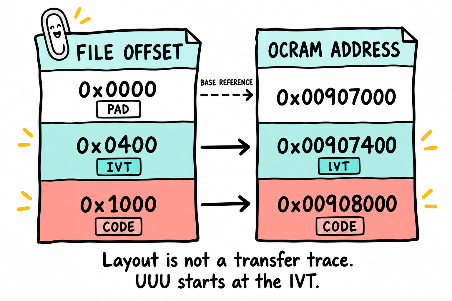
Each row pairs a file offset with its intended RAM address. base + file_offset describes the layout, not the bytes actually transferred. In our later UUU path, the upload starts at the IVT and skips the leading 0x400 padding bytes. For uploaded bytes, RAM = self + (file_offset - 0x400). The rows are not to scale. These arrows are not MMU translations.
Here is the same correspondence, including BootData:
File view |
Intended RAM coordinate |
|---|---|
SD offset |
OCRAM address |
SD offset |
OCRAM address |
SD offset |
OCRAM address |
SD offset |
OCRAM address |
In OCRAM at address 0x00907400, the IVT contains:
Offset    Field      Value
+0x00     header     0xD1 0x00 0x20 0x40
+0x04     entry      0x00908000
+0x08     reserved1  0x00000000
+0x0C     dcd        0x00000000   (no DCD for this tiny OCRAM-only image)
+0x10     boot_data  0x00907420   (BootData starts immediately after IVT)
+0x14     self       0x00907400   ← the address of this IVT
+0x18     csf        0x00000000   (no signature)
+0x1C     reserved2  0x00000000
The linker placed _start at 0x00908000; the IVT’s entry field gives that address to the ROM. Chapter 9 supplies the first wrapper with this no-DCD layout, and Chapter 11 generalizes it. The whole image must still fit in Chapter 5’s ROM-active OCRAM window.
7.4 BootData, telling the ROM how big the image is
The IVT gives the ROM a pointer to BootData. This next structure answers two practical questions: where should the image be loaded, and how many bytes belong to it? It occupies 12 bytes:
Offset |
Field |
Description |
|---|---|---|
|
|
Physical address to load the image to. |
|
|
Number of bytes to load (including the IVT, DCD, and padding). |
|
|
0 = normal image. A nonzero value selects a plugin image. We will not use plugins. |
In our padded file, start is the RAM address corresponding to file offset zero. length covers the complete file, including its padding and headers, not just .text. If you count only the instructions, you can leave later initialized data out of the transfer. A different image generator may use a different file layout, so derive these values from that layout rather than the extension.
7.5 The DCD, Device Configuration Data
OCRAM let our small image avoid a circular problem: code destined for DDR cannot first rely on unconfigured DDR to run the code that prepares it. For a larger image, someone must initialize the controller before that transfer. Who can do the work while the main program is not yet loaded?
Device Configuration Data, or DCD, is one answer. It contains commands the ROM performs before loading the main image, commonly register writes for clocks and DDR initialization. These are data records interpreted by the ROM, not Arm instructions compiled from our application.
Some commonly used command tags are:
Opcode |
Name |
Description |
|---|---|---|
|
WRITE |
Write value(s) to register(s) |
|
CHECK |
Poll register until condition is met |
|
NOP |
No-op |
The reference manual defines additional commands. WRITE and CHECK are the commands most relevant to the examples in this book.
WRITE format
0xCC <length:2-bytes-BE> <flags:1-byte> <addr0:4> <val0:4> <addr1:4> <val1:4> ...
The parameter uses width in bits 2:0 as a byte count; bit 3 is Mask and bit 4 is Set [RM Tables 8-29/8-30]. All address/value pairs in one command use that parameter:
bits:        7 6 5 | 4   | 3    | 2 1 0
             0 0 0 | Set | Mask | width
0x04:        0 0 0 | 0   | 0    | 1 0 0   plain 32-bit write
0x0C:        0 0 0 | 0   | 1    | 1 0 0   clear selected word bits
0x1C:        0 0 0 | 1   | 1    | 1 0 0   set selected word bits
Addresses and values in these command records are big-endian, unlike the IVT pointer words. DCD is not arbitrary reset-time MMIO: each address must be in the SoC’s permitted ranges [RM Table 8-31], aligned for the selected width, with a fitting value/mask. Invalid parameters can reject an entire multiwrite command. A familiar GPIO or watchdog write is not automatically permitted just because it works in later bare-metal code.
CHECK format
0xCF <length:2-bytes-BE> <flags:1-byte> <addr:4> <mask:4> [count:4-bytes-BE]
CHECK reads addr, applies mask, and tests the selected condition. Its flags do not mean the same operation as WRITE’s set/clear flags. For a 32-bit word [RM Tables 8-32 through 8-34]:
Parameter |
Condition on the selected bits |
|---|---|
|
All clear |
|
All set |
|
At least one clear |
|
At least one set |
Without count, this 12-byte command polls indefinitely. With the optional word it is 16 bytes and polling is bounded; count zero performs no polling. A count is not a documented duration in milliseconds. For example, a PLL-lock wait needs the correct bitmask, condition, and permitted register, not merely a CHECK tag copied after a write.
A minimal DCD
Format-only, not a runnable DDR setup: this byte record would write 0x12345678 to 0x80000000. Do not submit it on a freshly reset board: DDR at that address has not been initialized. The first OCRAM image uses no DCD.
0xD2 0x00 0x10 0x41      # RM-format DCD header, 16 bytes total
0xCC 0x00 0x0C 0x04      # WRITE command, 12 bytes, 32-bit width
0x80 0x00 0x00 0x00      # address = 0x80000000
0x12 0x34 0x56 0x78      # value
This DCD is 16 bytes total: a 4-byte DCD header followed by one 12-byte WRITE command. A DDR initialization DCD is often several hundred bytes because it contains many register writes.
This format-only record follows the RM’s documented version 0x41. U-Boot v2024.01’s image constants use 0x40; the exact tool/silicon combination must be validated before turning a DCD into a runnable setup. Our first image uses no DCD and does not depend on resolving that compatibility question. The documented maximum DCD size is 1,768 bytes.
Why DCD exists
There are two ways out of that ordering problem. Give the ROM a DCD so it can prepare DDR before transferring the main image there. Or give it a small Secondary Program Loader (SPL) that fits in OCRAM; the SPL initializes DDR and loads the larger stage itself. The register work can be similar, but who performs it and when are different.
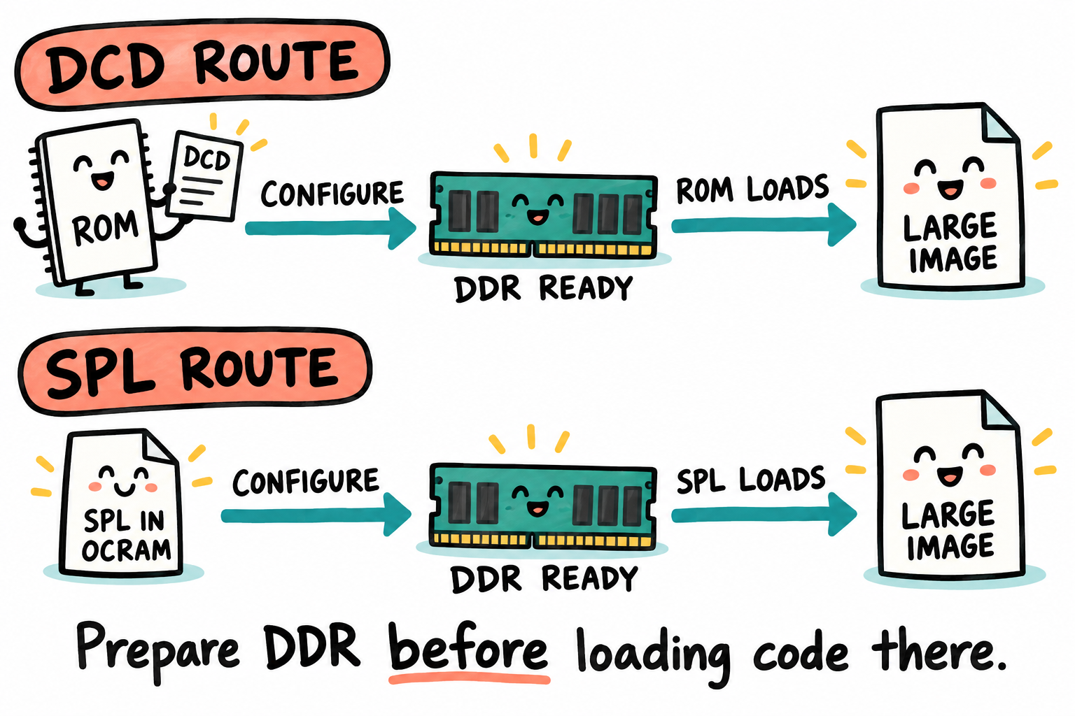
DDR must be ready before the larger program is loaded there. In the DCD route, the ROM reads configuration records. In the SPL route, a small program running in OCRAM does the work. The two rows show alternatives. Our first OCRAM-only image needs neither a DCD nor an SPL.
We set the first image’s DCD pointer to zero. Later code configures DDR when we reach that experiment; Chapter 11 keeps the OCRAM/no-DCD design. Do not copy a DDR DCD from an unrelated board as a compulsory header block.
7.6 Boot modes, in concrete detail
The header cannot help if the ROM is looking on a different device. The boot-mode signals answer that earlier question: where should it look? Keep the decision table in Section 7.2 beside the two routes below, and remember that a board’s switch label represents a particular signal pattern.
Internal Boot (BOOT_MODE = 10)
The ROM reads BOOT_CFG1[7:0], BOOT_CFG2[7:0], BOOT_CFG4[7:0] from the boot-mode pins (or from fuses if BT_FUSE_SEL is set). The bit patterns encode:
Device-class field |
Meaning |
Additional configuration |
|---|---|---|
|
SD/MMC class |
Controller, width, speed/protocol and other fields in RM SD/MMC tables |
|
NAND class |
Geometry and NAND-specific boot configuration |
|
Serial ROM through ECSPI |
Port/chip-select/addressing fields, RM Table 8-20 |
|
QuadSPI class |
Interface and other fields, RM Table 8-22; interface bit 3 value 1 is reserved |
These entries identify device classes. They are not complete board settings: controller selection, storage details, and board wiring supply other bits. Chapter 8 decodes the reference selector, so do not try to assemble a switch pattern from this class table alone or change boot fuses for these examples.
The Point Atom MINI boot selector exposes four labeled modes: SD, eMMC, NAND, and USB. SD, eMMC, and NAND are internal-boot configurations. USB selects Serial Downloader mode. The fitted storage depends on the core-board variant.
Serial Downloader (BOOT_MODE = 01)
The i.MX6ULL USB downloader identity is VID 0x15A2, PID 0x0080, corroborated by NXP’s UUU device table. The RM also describes SDP through UART1/UART2. Keep serial receive activity quiet during USB startup: a UART data-ready event, including noise, can select the UART downloader [RM 8.9.2]. We use USB for the early downloads and the UART later for our program’s text.
In SDP mode the ROM accepts a small command set:
0x0101READ_REGISTER0x0202WRITE_REGISTER0x0404WRITE_FILE, push bytes to a target address0x0505ERROR_STATUS0x0A0ADCD_WRITE0x0B0BJUMP_ADDRESS, process a previously-loaded image’s IVT
The identifiers come from RM Table 8-42. You will not need to type them or implement their USB exchange; uuu does that work. For our image, it uploads the IVT and following bytes, then asks the ROM to process the IVT. The header still supplies the final branch destination through IVT.entry.
USB mode provides the recovery path used throughout this book. If the Boot ROM enters SDP and accepts commands, software can still be loaded without relying on the installed flash contents.
7.7 The .imx image format
The name .imx tells us the file is intended as an i.MX boot artifact, but not which padding convention its generator used. Our padded raw image has the no-DCD layout below and is written at card byte zero:
File offset    Content
0x0000         1 KB padding; no partition table in the tiny Part II image
0x0400         ┌─ IVT (32 bytes)
0x0420         │  BootData (12 bytes)
0x042C         │  padding (a later DCD layout must define its own location)
0x1000         │  Application image proper (.text, .rodata, .data)
   ...         │
              ─┘  end after BootData.length bytes
The layout must satisfy both early acquisition and final placement: applicable IVT/BootData/DCD structures fit the device’s initial-read region; self describes the IVT destination; entry matches the linked code; and length covers the image’s complete defined extent. Final pointer arithmetic alone is not sufficient.
Here is an easy mistake to catch on paper. Our padded file already puts the IVT at file offset 0x400. Writing that file at card offset 0x400 would put the IVT at 0x800, not where the ROM expects it for this SD layout. Another generator may put the IVT first and require the 0x400 card write offset. Both conventions can be correct; mixing them is not:
Artifact |
IVT file offset |
Card write offset |
Resulting IVT card offset |
|---|---|---|---|
Book’s padded raw image |
|
|
|
Conventional IVT-first |
|
|
|
Check the actual generator/version before writing. The small Part II card has no partitions. When a later Linux image adds partitions, reserve the boot region explicitly; ordinary GPT puts its primary partition-entry array at LBA 2, conflicting with an IVT at byte 0x400. A later-starting MBR partition layout is a different contract. See UEFI GPT layout.
Tools that can generate IMX boot artifacts:
mkimage -T imximage -n image.cfg -d app.bin app.imx: syntax illustration only, not a runnable alternative here. It needs a supplied configuration, entry/load settings, and a placement check. See U-Boot v2024.01 imximage.c.Our own wrapper in Chapter 11. A small Python program constructs the header fields and combines them with the application bytes, without using
mkimage.
By writing the small wrapper ourselves, we can inspect exactly how its fields were chosen. When we later use mkimage or U-Boot’s image configuration, the tool will be automating a format we have already followed by hand.
7.8 HAB, High Assurance Boot, briefly
A correctly laid-out image tells the ROM where its pieces belong; it does not establish whether they are trusted. A production device may also require an answer to “who signed this?” HAB, High Assurance Boot, is NXP’s ROM secure-boot scheme. The IVT’s csf field points to its Command Sequence File authentication data, produced with the Code Signing Tool, CST. HAB uses a fuse-stored Super Root Key (SRK) hash, certificates, and signatures to apply the provisioned trust policy.
Open-mode authentication failures do not necessarily block execution. Closed-mode policy requires valid authentication; closing the device is irreversible. An incorrectly signed image can sometimes be replaced through an authenticated recovery path using the provisioned trust configuration. Lost signing keys or unusable trust provisioning are different, potentially unrecoverable failures. SDP does not bypass closed-mode authentication.
We will not enable HAB in Parts I-VI of this book. Chapter 124 covers the full HAB workflow, including how to sign U-Boot and the kernel and how to extend verification to the root filesystem.
For the unsigned teaching images here, leave IVT.csf = 0. Do not touch SEC_CONFIG fuses. Image layout and image trust are separate questions; we only need to solve the first one for these early experiments.
7.9 How to inspect an .imx image
After Chapter 11 creates an .imx file, inspect it with:
$ xxd -s 0x400 -l 32 app.imx
For the worked example in Section 7.3, the 32 IVT bytes at file offset 0x400 are:
d1 00 20 40  00 80 90 00  00 00 00 00  00 00 00 00
20 74 90 00  00 74 90 00  00 00 00 00  00 00 00 00
The header stores its length bytes in big-endian order, as required by the IVT format. The pointer fields are 32-bit little-endian values:
Bytes |
Field |
Decoded value |
|---|---|---|
|
header |
tag |
|
entry |
|
|
reserved1 |
0 |
|
dcd |
no DCD |
|
boot_data |
|
|
self |
|
|
csf |
unsigned image |
|
reserved2 |
0 |
Pick the entry field out of the dump: 00 80 90 00 decodes to the 0x00908000 address we chose earlier. The layout has become actual bytes we can inspect. Compare Chapter 11’s output field by field, remembering that the header length and the pointer words use different byte-order rules. A file appearing in the directory is only the beginning of that check.
Do not use dumpimage -l as a promised validator for this custom padded/no-DCD file: tool support depends on header placement and format. Inspect these exact bytes and pointer relationships first; successful structural checks still do not prove execution.
7.10 Key Notes
The Boot ROM is a loader with a fixed contract. The IVT names the entry point and associated structures, BootData describes the loaded extent, and DCD supplies initialization before application code can run.
File offsets, media offsets and physical RAM addresses are different coordinate systems. Pointer differences must agree with the image layout, but a valid-looking header does not prove that the board’s DDR settings are correct.
The worked OCRAM image has no DCD because its first instructions do not depend on external memory. A DDR-based image needs a documented initialization path, whether that responsibility belongs to ROM-executed DCD or to SPL.
Boot-mode pins select a ROM path at the documented reset boundary. Switch markings alone do not reveal the sampled bit values, and a warm reset is not a substitute for the specified cold-start procedure.
HAB changes which images the ROM accepts. Image inspection is reversible, but closing security fuses is not an ordinary configuration step.
7.11 Pitfalls
IVT.selfconfused with a file offset. An inconsistent self-pointer can break the ROM’s interpretation of the associated structures. Checkselfagainst the IVT’s intended physical address after loading, and check the pointer differences against the file layout. A silent board does not tell you which of those checks failed.BootData.lengthshorter than the image. Tail of your image is not loaded..datainitial values become whatever was in RAM.Unbounded DCD CHECK. Without a poll count, a condition that never changes can block progress indefinitely. A bounded count does not by itself prove valid hardware initialization. To recover, disconnect boot-power paths, select USB while unpowered, and use Chapter 8’s documented cold-start sequence before loading a corrected image. Security policy still applies.
Wrong DCD lengths or byte order. Header/command lengths are big-endian. A malformed record can fail parsing/validation or misidentify the following records, preventing boot. Decode its lengths and boundaries before transfer; DCD is not unchecked executable code.
Mixing file and media offsets. The book’s padded file goes at card byte zero; an IVT-first boot blob uses another write offset. Generic partitioning, especially GPT, can overwrite the boot region. Recheck the exact layout before writing.
Closing HAB by accident. It is a one-way fuse. Do not write to OCOTP_CFG5 unless you have read Chapter 124 carefully and have a key-management plan.
7.12 Going deeper
IMX6ULLRM, Chapter 8, System Boot. The authoritative reference.
For NAND and QSPI, start with the device-specific sections of IMX6ULLRM Chapter 8 and verify any application note’s actual title and scope.
AN4581: i.MX 6 Series Boot Process.
U-Boot
tools/mkimage.candtools/imximage.c, which implement the production image-generation path.U-Boot v2024.01 image constants, for this tool’s media offsets and header encodings. Do not substitute the separate later-family
imx-mkimagecontainer workflow for this i.MX6ULL route.
We have followed an instruction from its linked address to the header field that names it, and followed that header back to its position in the file. The numbers agree on paper. Next we need a physical connection to the chip that will read them. The Boot ROM can expose its USB downloader before our program runs; Chapter 8 checks that path on the actual board.