Chapter 24J: SPI LCD and I2C OLED displays in U-Boot
An SPI transfer succeeds, yet the screen does not change. That is possible: SPI reports whether the controller moved bits, not whether those bits were the panel’s commands, used the right D/C level, or reached initialized pixel memory. An I2C ACK is similarly narrower than a visible OLED image.
This chapter follows those bytes to a small status display. We use upstream U-Boot v2026.04, distinguish its drivers from Linux’s, and provide a bounded SSD1306 command for one documented module profile. The supplied MINI V2.2 has no fitted SPI LCD or I2C OLED. Its RGBLCD socket belongs to Chapter 24I; a small serial display is an added module. We use the actual P4 expansion routes below, with a shared P1/I2C2 alternative for an OLED. The guide’s ALPHA I2C/SPI sensor labs are not evidence that their devices exist on MINI.
Begin with Chapter 19’s MINI vendor baseline and UART1 console. The bus
mapping below comes from the supplied MINI/core schematics; the code targets
the separate v2026.04 mx6ull_pa_mini migration, not a drop-in vendor
patch. Keep UART1 for diagnostics while bringing up the added module.
24J.1 First decision: what kind of display is it?
Display |
Bus/memory |
Path in this chapter |
|---|---|---|
Parallel RGB panel |
eLCDIF scans a RAM framebuffer |
Chapter 24I’s DM video path |
ST7735/ST7789/ILI9341-type color module |
SPI commands and controller pixel RAM |
Board-specific transport/init unless a verified driver implements the required path |
SSD1306 monochrome module |
I2C commands and page-organized display RAM |
Bounded board-local status command |
SH1106 module |
Similar-looking but different addressing/geometry |
Its own driver/profile, not the SSD1306 command below |
Smart UART display |
Module-specific serial protocol |
Separate product integration |
The v2026.04 drivers/video/ tree has no matching ST7735, ST7789, ILI9341,
SSD1306, or SH1106 driver for these examples. A Linux-compatible string does
not create a U-Boot driver. In particular, a panel-initialization driver is
not necessarily a DM video driver that allocates a framebuffer and flushes
pixels over SPI.
Use a full framebuffer only when you need it and have the complete transport integration. A rectangle indicating service mode needs far less code, but still needs correct initialization and errors. Calling the routine “tiny” does not exempt it from those requirements.
For a first MINI extension, a documented 128 x 64 I2C SSD1306 module with 3.3 V-compatible supply/logic and the specified charge-pump profile needs fewer control wires than a color SPI LCD. Use I2C1 on P4 as described in Section 24J.8. A color module additionally needs a reviewed D/C, reset, backlight and initialization path; the transport helper alone will not display an image. Neither module is part of the stock-board acceptance test.
24J.2 What belongs in U-Boot?
Useful early states include boot attempt, recovery service, refusal reason, and a defined factory result. Show update progress only after verified work actually advances; transferring bytes into a buffer is not a committed flash update. Do not display PASS before the check succeeds.
Keep the serial console as the authoritative diagnostic path. A display may itself be the failed optional peripheral. Rendering it must not enable an unsafe rail, bypass a power veto, or block watchdog service indefinitely. Linux takes over the display after its own driver initializes it; U-Boot’s status routine is not the product UI.
24J.3 SPI LCD hardware checklist
Signal/condition |
Evidence needed |
|---|---|
SCLK/MOSI/CS |
Actual ECSPI controller, pad routing, chip select, SPI mode and allowed frequency |
MISO |
Whether connected and whether reads are supported; write-only panels cannot prove identity by readback |
D/C |
Command/data polarity and setup time relative to CS/clock |
RESET |
Assertion polarity, pulse width, delay after release |
Backlight |
Separate driver/enable/PWM polarity and safe startup order |
VCC/IOVCC |
Correct voltage levels, power sequence, no powered GPIO back-feed |
Geometry |
Controller RAM size, visible window offsets, rotation and RGB/BGR order |
MINI sheet 3’s P4 exposes a useful ECSPI3 route, verified against the v2026.04 i.MX6UL pin-function definitions:
P4 pin |
Schematic net / SoC pad |
ECSPI3 function |
|---|---|---|
17 |
UART2_TXD / UART2_TX_DATA |
SS0 (native chip select) |
18 |
UART2_RXD / UART2_RX_DATA |
SCLK |
19 |
UART2_RTS / UART2_RTS_B |
MISO |
20 |
UART2_CTS / UART2_CTS_B |
MOSI |
The UART labels name physical routes, not the selected function. Disable
UART2 ownership and configure the corresponding __ECSPI3_* pinmux plus
the ECSPI3 controller in U-Boot’s control DT. Do not use ALPHA’s sensor
connector wiring or switch ENET2 pads away from the MINI’s onboard PHY.
Confirm P4 pin 1/orientation on the actual assembly before attaching wires.
P4 pin 47 is ground, 48 DCDC_3V3, and 46 DCDC_5V. These are board supply nets, not interchangeable module voltages; check the module’s supply and IO levels, pull-ups, current budget and power-off behavior. D/C/reset and backlight still need separately assigned GPIOs/module circuits. UART1_CTS/GPIO1_IO18 is MINI KEY0; GPIO1_IO01 carries GBC_KEY/AP_INT, not that switch. GPIO1_IO03 is LED0, GPIO1_IO08 RGB backlight, and SNVS_TAMPER1/GPIO5 bit 1 BEEP through an active-low PNP switch. GPIO1_IO04 also reaches camera PWDN, and GPIO1_IO02 camera RESET. A header pin is not automatically unowned: review accessories and the control DT before selecting the additional outputs.
A typical controller sequence includes reset, sleep exit and its delay, power/gamma configuration, pixel format, memory orientation, a visible column/row window, pixel data, display-on, and backlight. The exact command bytes and delays come from the controller and module specification. ST7789, ST7735, and ILI9341 sequences are not interchangeable.
24J.4 SPI LCD: Device Tree shape
Describe the real ECSPI bus, pinmux, and chip select. A display child needs
its actual reg chip-select index and spi-max-frequency; mode properties,
D/C/reset GPIOs, and any power/backlight links must match the driver you are
actually writing. Do not add sitronix,st7789v and expect v2026.04 to bind a
missing driver.
Property/group |
What it establishes |
|---|---|
Bus pinctrl |
SCLK/MOSI and any MISO route; separate D/C/reset/CS GPIO pad groups where needed |
|
The verified selected device, not an assumed GPIO4 bit 26 |
Child |
SPI chip select, not a memory address |
|
A reviewed bus limit, not a calibrated transfer rate |
Driver-consumed GPIO properties |
Ownership/polarity only if the implementation requests them |
Width/height/rotation |
Useful only if the chosen driver parses them |
For an initial command-driven prototype, bind a reviewed generic SPI child or the new board-local driver and request GPIO descriptors explicitly. Generic SPI binding does not reset the LCD or render pixels. A future video driver must provide geometry/storage, draw/flush behavior, and error handling; a panel node alone is not that implementation.
24J.5 SPI LCD: useful configs
The i.MX bus foundation is:
CONFIG_SPI=y
CONFIG_DM_SPI=y
CONFIG_MXC_SPI=y
CONFIG_CMD_SPI=y
CONFIG_DM_GPIO=y
CMD_SPI adds sspi, not a command named spi. Check help sspi on the
actual build. Its arguments include a bit count, not a byte count. Its small
command buffer is not a frame uploader; do not paste unbounded pixel hex
strings. A transfer also needs the right D/C state, which sspi does not
configure for you.
If implementing a real DM video driver, use CONFIG_VIDEO and the required
BMP formats as in Chapter 24I; CONFIG_DM_VIDEO is not a v2026.04 symbol.
Do not enable generic video and claim it supplies the absent panel driver.
Build the same MINI port with Chapter 3’s sourced environment and a separate
O= directory. Bus compilation does not validate the added module wiring.
24J.6 SPI LCD manual bring-up order
First keep the backlight disabled and review the electrical/reset sequence. Verify the bus/pad route, then use an approved analyzer connection to inspect a small, documented command transaction. A write-only transfer returning zero cannot distinguish an absent panel from a correctly connected one.
This transport helper, not a complete panel driver, sends one command and up to 512 data bytes with CS held across the D/C change. It assumes a probed SPI child device and an already requested D/C descriptor whose logical 0 is command and 1 is data:
#include <dm.h>
#include <spi.h>
#include <asm/gpio.h>
#include <linux/errno.h>
#include <linux/types.h>

static int lcd_command(struct udevice *child, struct gpio_desc *dc,
                       u8 command, const u8 *data, unsigned int len)
{
    int ret;

    if (len > 512 || (len && !data))
        return -EINVAL;
    ret = dm_spi_claim_bus(child);
    if (ret)
        return ret;
    ret = dm_gpio_set_value(dc, 0);
    if (ret)
        goto release;
    ret = dm_spi_xfer(child, 8, &command, NULL,
                     SPI_XFER_BEGIN | (len ? 0 : SPI_XFER_END));
    if (ret)
        goto end;
    if (len) {
        ret = dm_gpio_set_value(dc, 1);
        if (ret)
            goto end;
        ret = dm_spi_xfer(child, len * 8, data, NULL, SPI_XFER_END);
        if (ret)
            goto end;
    }
    goto release;
end:
    /* Best effort to release CS; preserve the original error. */
    dm_spi_xfer(child, 0, NULL, NULL, SPI_XFER_END);
release:
    dm_spi_release_bus(child);
    return ret;
}
The byte bound makes len * 8 safe and keeps the buffer contract explicit.
The supplied buffer must really contain len bytes. A cleanup error cannot
prove CS returned idle: report the original error and stop that display path,
then use the board’s approved reset/recovery procedure. The helper does not
supply reset, delays, bus speed/mode, or rail initialization. Add required D/C
setup/hold delays if the selected controller’s specification needs them.
After a documented initialization, set a small column/row window using the
controller’s required high-byte/low-byte order, then write a known pixel
pattern. For an RGB565 mode, red is the byte pair f8 00, green 07 e0, and
blue 00 1f if the selected mode is high-byte-first RGB. Sending a native
little-endian u16 array reverses those bytes. RGB/BGR settings can change
the visible colors too.
The bounded helper is not a whole-screen fill engine. A 16 x 16 RGB565 window needs 512 pixel bytes; a larger frame needs a reviewed streaming/chunking routine that preserves controller address state and watchdog scheduling. Do not restart RAM-write at the origin for every chunk and call that a fill. Prove color/window mapping before adding text. Without module-specific init, this SPI path remains an implementation example, not a ready-to-use driver.
24J.7 I2C OLED: why it feels different
An SSD1306 has display RAM too. In its page organization, one byte controls
eight vertical pixels at one column. A 128 x 64 image needs
128 * (64 / 8) = 1024 data bytes. There is no separate backlight: OLED
pixels emit light.
In I2C mode, a control byte precedes the payload. 0x00 selects a command
stream; 0x40 selects display data. These are not register addresses.
The first payload byte must not be preceded by an extra register-offset byte
inserted by a generic I2C helper.
SSD1306 modules may use 7-bit address 0x3c or 0x3d, but verify the fitted
strap/module. Some modules are SPI, 128 x 32, externally supplied, or contain
SH1106 instead. A matching outline or an ACK does not establish this profile.
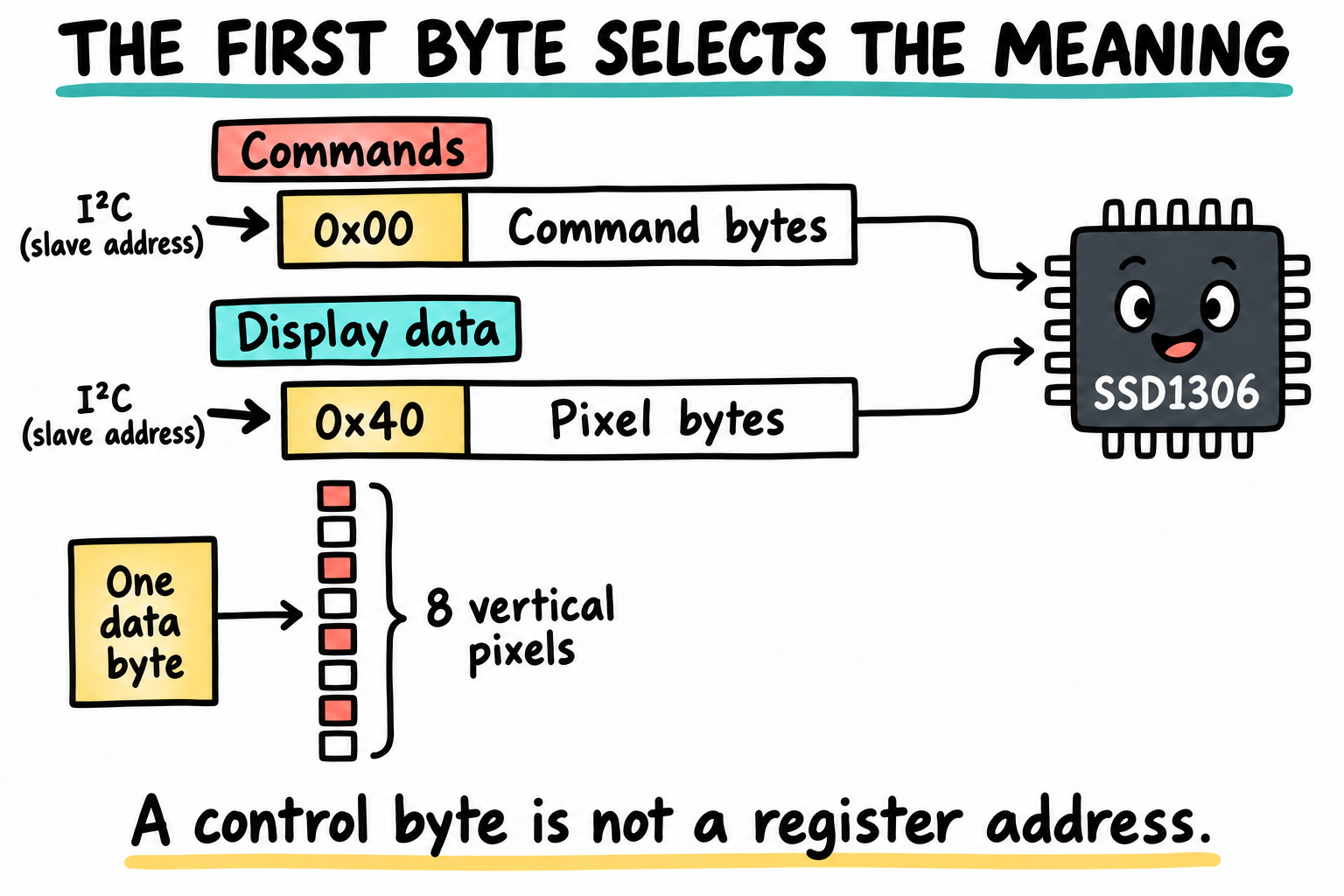
The control byte selects how the SSD1306 interprets the following bytes. It is not a register address, and no extra offset byte belongs before it. The pixel column illustrates page organization without claiming a fitted MINI display.
24J.8 I2C OLED Device Tree shape
Linux’s solomon,ssd1306fb-i2c binding does not imply a matching U-Boot driver.
Keep the two control trees and ownership stages distinct. The board command
below directly obtains a generic I2C chip on a verified bus/address.
On MINI, use I2C1 via P4 pin 43 UART4_TXD (SCL), pin 42 UART4_RXD (SDA),
and the reviewed supply/ground connections. Pin 41 is ENET1_RXER, not SCL;
pin 44 is UART5_RXD/I2C2 SDA, not I2C1 SDA. Do not infer UART or bus pairs
from adjacent header rows. MINI sheet 1 shows R42/R57
4.7 kOhm pull-ups to DCDC_3V3. Core sheet 6 and the upstream pin definitions
map these pads to MX6UL_PAD_UART4_TX_DATA__I2C1_SCL and
MX6UL_PAD_UART4_RX_DATA__I2C1_SDA. Disable UART4 on these pads, enable
&i2c1, and supply its IOMUXC pinctrl group with the board’s reviewed pad
settings. Account for the module’s own pull-ups rather than adding another
pair automatically. Keep UART1/USB_TTL as the console.
Use i2c bus to map this hardware I2C1 to its U-Boot sequence, then set
the command’s OLED_BUS accordingly. The 0 below is an example sequence,
not an assertion that every migrated DT assigns I2C1 sequence zero. I2C2
is also routed to the RGB touch/camera connectors, so it is not an isolated
spare bus on an accessorized MINI. Prefer the explicitly reviewed P4 route
for this first module instead of probing an unknown shared bus.
The layout also labels P1 OLED/CAMERA. Sheet 2 routes P1 pin 1 to DCDC_3V3, pin 2 to ground, pin 4 to I2C2 SCL and pin 6 to I2C2 SDA. A documented OLED adapter can use those wires after checking the shared camera/touch bus and module address. This is an alternative to P4/I2C1, not a promise that a generic four-pin OLED plugs into P1 directly; the connector’s other pins carry camera signals. Select the corresponding I2C2 pinmux and actual U-Boot bus sequence if taking this route.
For a dedicated U-Boot generic child, explicitly describing
u-boot,i2c-offset-len = <0> prevents register-offset insertion. Its chosen
compatible/driver must be reviewed; do not attach this property to an
unrelated chip or override a PMIC driver’s protocol. The command also sets
and checks zero offset length because the chip may already be bound.
Linux should receive its own supported display node and reset/power wiring.
24J.9 I2C OLED configs
Enable the actual bus and command support:
CONFIG_DM_I2C=y
CONFIG_SYS_I2C_MXC=y
CONFIG_CMD_I2C=y
CONFIG_DM_GPIO=y
BOARD_LATE_INIT is needed only if the integration uses that callback, not
for the command itself. First inspect i2c bus, bus aliases/pinmux, supply,
pull-ups, and reset wiring. Do not indiscriminately scan a shared PMIC bus.
A reviewed known-address check may establish an ACK, not chip identity or
successful display initialization.
24J.10 A tiny SSD1306 U-Boot command
This example covers only a verified 128 x 64 SSD1306 I2C module with the internal charge-pump profile described below. Before running it, the module must be powered and reset with its documented timing. Its segment/COM orientation, electrical settings, contrast, and power sequence must match its specification. Do not substitute a 128 x 32 or SH1106 module. The P4/I2C1 route above is documented MINI hardware; the particular module, address strap, reset and supply profile still need matching.
Create board/myorg/mx6ull_pa_mini/oled_ssd1306.c in your port. Change the
bus/address constants only after mapping the actual controller and strap:
// SPDX-License-Identifier: GPL-2.0+
#include <command.h>
#include <dm.h>
#include <i2c.h>
#include <stdio.h>
#include <linux/errno.h>
#include <linux/kernel.h>
#include <linux/string.h>

#define OLED_BUS       0       /* Must match the verified U-Boot bus sequence. */
#define OLED_ADDR      0x3c    /* Must match the module's 7-bit address. */
#define OLED_WIDTH     128
#define OLED_PAGES     8
#define OLED_CHUNK     16

static int oled_packet(struct udevice *dev, u8 control,
                       const u8 *data, unsigned int len)
{
    u8 buf[OLED_CHUNK + 1];

    if (!len || len > OLED_CHUNK || !data)
        return -EINVAL;
    buf[0] = control;
    memcpy(buf + 1, data, len);
    return dm_i2c_write(dev, 0, buf, len + 1);
}

static int oled_commands(struct udevice *dev, const u8 *data, unsigned int len)
{
    return oled_packet(dev, 0x00, data, len);
}

static int oled_init(struct udevice *dev)
{
    static const struct {
        u8 bytes[2];
        u8 len;
    } init[] = {
        { { 0xae, 0 }, 1 },       /* Display off until RAM is cleared. */
        { { 0xd5, 0x80 }, 2 },    /* Module profile: clock. */
        { { 0xa8, 0x3f }, 2 },    /* 64-row multiplex. */
        { { 0xd3, 0x00 }, 2 },    /* Display offset. */
        { { 0x40, 0 }, 1 },       /* Start line. */
        { { 0x8d, 0x14 }, 2 },    /* Internal charge pump profile. */
        { { 0x20, 0x02 }, 2 },    /* Page addressing, matching drawing below. */
        { { 0xa1, 0 }, 1 },       /* Segment remap. */
        { { 0xc8, 0 }, 1 },       /* COM scan direction. */
        { { 0xda, 0x12 }, 2 },    /* 128x64 COM pin profile. */
        { { 0x81, 0x7f }, 2 },    /* Profile contrast, not a measured optimum. */
        { { 0xd9, 0xf1 }, 2 },    /* Charge-pump precharge profile. */
        { { 0xdb, 0x20 }, 2 },    /* Documented VCOMH encoding. */
        { { 0xa4, 0 }, 1 },       /* Display RAM, not all-pixels-on. */
        { { 0xa6, 0 }, 1 },       /* Normal polarity. */
        { { 0x2e, 0 }, 1 },       /* Scrolling disabled. */
    };
    unsigned int i;
    int ret;

    for (i = 0; i < ARRAY_SIZE(init); ++i) {
        ret = oled_commands(dev, init[i].bytes, init[i].len);
        if (ret)
            return ret;
    }
    return 0;
}

static int oled_draw(struct udevice *dev, int bar)
{
    u8 pixels[OLED_CHUNK];
    unsigned int page, col;
    int ret;

    for (page = 0; page < OLED_PAGES; ++page) {
        u8 position[] = { 0xb0 + page, 0x00, 0x10 };

        ret = oled_commands(dev, position, sizeof(position));
        if (ret)
            return ret;
        memset(pixels, bar && page < 2 ? 0xff : 0, sizeof(pixels));
        for (col = 0; col < OLED_WIDTH; col += OLED_CHUNK) {
            ret = oled_packet(dev, 0x40, pixels, sizeof(pixels));
            if (ret)
                return ret;
        }
    }
    return 0;
}

static int do_oled(struct cmd_tbl *cmdtp, int flag, int argc, char *const argv[])
{
    struct udevice *dev;
    const u8 on = 0xaf;
    int bar, ret;

    if (argc != 2)
        return CMD_RET_USAGE;
    if (!strcmp(argv[1], "clear"))
        bar = 0;
    else if (!strcmp(argv[1], "bar"))
        bar = 1;
    else
        return CMD_RET_USAGE;

    ret = i2c_get_chip_for_busnum(OLED_BUS, OLED_ADDR, 0, &dev);
    if (ret)
        goto fail;
    ret = i2c_set_chip_offset_len(dev, 0);
    if (ret)
        goto fail;
    ret = oled_init(dev);
    if (ret)
        goto fail;
    ret = oled_draw(dev, bar);
    if (ret)
        goto fail;
    ret = oled_commands(dev, &on, 1);
    if (ret)
        goto fail;
    return CMD_RET_SUCCESS;
fail:
    printf("OLED transfer failed on bus %d address 0x%02x: %d\n",
           OLED_BUS, OLED_ADDR, ret);
    return CMD_RET_FAILURE;
}

U_BOOT_CMD(oled, 2, 0, do_oled,
           "draw a checked SSD1306 module status pattern",
           "clear - initialize, clear RAM, then enable display\n"
           "oled bar - draw a 16-pixel-high band (not update progress)");
Each command and its argument stay in one bounded packet. Drawing uses
page addressing (0x20,0x02) followed by the matching page/column
commands. Each page contains eight 16-byte data packets. The first two pages
form a 16-pixel band; this is a recognizable marker, not a percentage gauge.
The entire RAM is written before display-on, avoiding stale pixels at startup.
If any transfer fails, stop and return failure; partially changed pixels must
not be interpreted as a valid result.
The command encodings were checked against Solomon Systech’s SSD1306 Rev 1.1
command tables and its charge-pump application note, available in this
manufacturer document hosted by Focus LCDs.
The document specifies page mode, control bytes, and the VCOMH 0x20 encoding;
it does not qualify the supply/reset design of an unknown module.
Add the object to the existing board Makefile only for the selected optional feature, or for a dedicated example build:
obj-y += oled_ssd1306.o
Then build with the selected Linux Arm compiler as in Chapter 24F. On an
approved matching module, oled clear and oled bar are the manual checks.
oled typo or missing arguments must return usage before any bus access.
There is no successful hardware log promised here. A host transfer fixture
can verify bytes and failures; it cannot qualify OLED voltages or reset timing.
24J.11 Showing status automatically
Only after manual qualification, add a RAM-only optional wrapper to the existing normal A/B path. Use it only from an approved normal-boot console, not one stopped by a recovery or power veto:
pa-mini=> setenv show_oled 'oled bar'
pa-mini=> setenv normal_with_oled 'run show_oled; run boot_selected'
pa-mini=> setenv bootcmd 'run normal_with_oled'
pa-mini=> run normal_with_oled
If the RGB splash is also used, integrate both optional commands into one
normal wrapper. Do not replace the port with an assumed distro_bootcmd,
and do not blindly saveenv an experimental display hook. Retain the
alternate rollback command and the recovery/power overrides. Optional display
failure may be reported without blocking normal boot if the hardware is safe.
The last command tries Linux in this session. Resetting without saving reloads the earlier stored policy. A compiled board hook runs at a different time: review its interaction with the whole-environment bootcount save, as in 24G/H.
For a power fault, serial-only reporting is the default: initializing an
optional display can draw exactly the current the policy is refusing. A
rollback/recovery-specific symbol needs a defined renderer and qualified
hook; oled bar alone does not distinguish those states. Do not call a
static helper from another board source file without providing a proper
interface and linking it deliberately.
24J.12 Which path should you choose?
Requirement |
Implementation boundary |
|---|---|
Full RGB logo |
Chapter 24I’s verified video driver and trusted BMP path |
SPI LCD with no upstream driver |
Module-specific reset/init plus bounded transactions, then a real draw/flush implementation |
SSD1306 marker on the exact profile |
The board command above, after hardware qualification |
Text, fonts, percentage progress |
Additional renderer, clipping/bounds, real state source and transfer/error tests |
Shared Linux display |
Separate Linux driver/DT initialization and intentional handoff |
Safety-critical indication |
Defined indication semantics and independent failure behavior; not merely a colored shape |
The first useful result is a small, explainable pattern with known bytes. Do not call it a working graphics stack or production status display before its missing layers have been built and tested.
24J.13 Pitfalls
Linux driver names used as U-Boot support evidence. Check this release’s tree.
SPI success treated as panel ACK. SPI has no automatic device ACK.
Byte count passed as bit count.
dm_spi_xfertakes bits.Native
u16pixels on a high-byte-first wire. Construct the actual bytes.D/C or CS broken across a command/data pair. Inspect the whole transaction.
Extra I2C offset byte. SSD1306 requires its control byte first.
Horizontal mode mixed with page commands. Initialization and drawing must agree.
SH1106 or 128x32 treated as this module. Geometry and commands differ.
A display hook bypassing A/B or safety. Optional feedback must retain policy.
24J.14 Key Notes
The stock MINI has neither serial display, and v2026.04 lacks the named panel drivers used in these examples. A compatible string or working bus driver does not supply reset, initialization or rendering.
SPI command/data transfers depend on D/C and CS across the entire transaction. The bounded helper owns bus claim/release and length checks, but not panel timing or a whole-screen streaming engine.
dm_spi_xfercounts bits, while RGB565 wire order is a byte-level contract. Native little-endian pixel arrays do not automatically match high-byte-first panel modes.SSD1306 I2C packets start with command/data control bytes, not register offsets. Zero offset length, page-mode initialization and page/column writes must agree for all 1024 pixel bytes.
The supplied OLED command covers only its documented 128 x 64 charge-pump profile. An ACK, similar module shape or SH1106 name does not establish that profile.
P4 bus routes share pads with UART functions, and P1/I2C2 shares accessories. Module voltage, pull-ups and separate GPIO ownership remain hardware contracts beyond byte-transaction correctness.
Optional indication retains serial diagnostics and boot/recovery/power precedence. Partial pixels after a transfer failure and a decorative bar are not verified status or committed update progress.
24J.15 Going deeper
Supplied MINI V2.2 schematic, sheets 1-3, and core sheets 5-6/8: P4 bus routes, existing GPIO owners and I2C pull-ups. The guide’s applicability table (pp. 7-8) excludes the stock MINI from its ALPHA I2C/SPI sensor labs.
v2026.04 i.MX6UL pin-function definitions: UART2-to-ECSPI3 and UART4-to-I2C1 alternate functions.
I2C API and I2C uclass: offset insertion and errors.
Solomon Systech SSD1306 product documentation, plus the fitted module’s documented initialization/power specification.
The actual ST7735/ST7789/ILI9341 or SH1106 manufacturer’s controller manual, matched to the module rather than a generic internet initialization list.
End of Part III.
We can now separate image choice from acceptance, service entry from ROM recovery, and a display indication from the operation it describes. The next part follows the kernel after U-Boot hands it the selected image and DTB.