Chapter 24B: U-Boot board policy with GPIO and I2C
A bootloader can read a temperature register correctly and still make the wrong decision. A truncated negative value, a stale saved bootcmd, or a recovery check followed unconditionally by normal boot can undo the intended gate. The important part is carrying the input all the way to the boot decision.
We will add a once-per-boot policy to the Chapter 22 MINI migration port. These examples target upstream U-Boot v2026.04, commit 88dc2788777babfd6322fa655df549a019aa1e69, with the established names:
board/myorg/mx6ull_pa_mini/mx6ull_pa_mini.c
configs/mx6ull_pa_mini_defconfig
arch/arm/dts/imx6ull-pa-mini.dts
include/configs/mx6ull_pa_mini.h
The supplied MINI V2.2 schematic gives us a real starting point: the stock KEY0 button and two routed I2C buses. The TMP102 at 0x48 is an optional external add-on, not an onboard temperature sensor. We will study its error handling on the host, then use KEY0 for a policy that needs no added sensor.
These are modern driver-model examples, not patches to paste into Chapter 19’s vendor U-Boot. The vendor baseline establishes the documented MINI starting point; compiling v2026.04 helpers does not establish a working modern MINI image. Keep the two source trees, configurations and build outputs separate.
MINI V2.2 resource |
Documented connection |
Use here |
|---|---|---|
KEY0 |
UART1_CTS pad / GPIO1_IO18; switch to ground, R12 10 kOhm to 3.3 V |
Stock recovery input. |
I2C1 |
UART4 TX/RX pads; P4 pin 43 is SCL, pin 42 is SDA when muxed to I2C |
Optional TMP102, later identity EEPROM. |
I2C2 |
UART5 TX/RX pads; P4 pin 45 is SCL, pin 44 is SDA, also RGBLCD J1 and camera P1 |
Leave to fitted display/touch/camera hardware. |
ON/OFF, RESET, BOOT_CFG1 |
Power control, shared hardware reset, ROM boot selection |
Not recovery GPIOs. |
This mapping comes from MINI schematic sheets 1-3 and CORE sheet 6. CORE connector aliases describe several possible baseboards; the MINI sheet decides what is actually connected. In particular, MINI SNVS_TAMPER0 is WIFI_REG_ON, not KEY0. The guide’s pp7-8 applicability table excludes the stock ALPHA I2C experiments on MINI; that is not the absence of an I2C controller or connector.
These checks run in full U-Boot after DDR initialization. The pinned mainline EVK reference uses ROM plus DCD and u-boot-dtb.imx, not SPL at a second storage offset. A late check cannot protect hardware during ROM/DCD initialization.
24B.1 What belongs in U-Boot policy
On an MCU you may own a peripheral for the application’s lifetime. Here U-Boot owns it only long enough to decide what to start. Linux initializes its own drivers afterward.
Decision |
Suitable scope |
|---|---|
Hold at the prompt because a measured condition forbids boot |
A bounded check, with a defined error policy. |
Select recovery while a key is held |
Read a dedicated input before dispatching either path. |
Choose an OS DTB from a board ID |
Validate identity first; Chapter 24D develops this. |
Maintain fan speed after Linux starts |
Linux thermal/PWM drivers, not a U-Boot polling loop. |
Manage a complex update transaction |
Usually a Linux recovery system; loading an image is a smaller job. |
Stopping at the prompt leaves the board powered. It is not thermal shutdown, and one sensor does not measure every junction. A safety requirement may need hardware supervision, power removal and a qualified thermal design. The 50 C threshold is a teaching value, not a board rating.
24B.2 Files changed in this chapter
File |
Responsibility |
|---|---|
|
Select interfaces, commands and the late hook. |
|
Describe MINI wiring and fitted add-ons in U-Boot’s control DT. |
|
Read inputs and dispatch policy once. |
|
Extend default environment without duplicate keys. |
The control DT describes hardware U-Boot itself uses. It is not the OS DTB later loaded at fdt_addr_r. Adding a sensor only to the OS DTB does not make it available to U-Boot’s driver model.
24B.3 Enable the needed U-Boot features
Merge these into the existing defconfig; this is not a complete defconfig:
CONFIG_BOARD_LATE_INIT=y
CONFIG_DM_GPIO=y
CONFIG_MXC_GPIO=y
CONFIG_DM_GPIO_LOOKUP_LINE_NAME=y
CONFIG_CMD_GPIO=y
CONFIG_DM_I2C=y
CONFIG_SYS_I2C_MXC=y
CONFIG_CMD_I2C=y
CONFIG_HUSH_PARSER=y
CONFIG_HUSH_OLD_PARSER=y
CONFIG_USE_BOOTCOMMAND=y
CONFIG_BOOTCOMMAND="run normal_boot"
SYS_I2C_MXC is the pinned controller symbol. Driver-model interfaces do not replace controller drivers or pad setup. Retain Chapter 22’s OF_CONTROL, i.MX pinctrl and other board settings. The command options add diagnostics; the C reader does not need those commands. No setexpr is needed.
Use the existing project setup in an Ubuntu Bash terminal:
. ~/imx6ull/scripts/env.sh
# Continue only if setup succeeded, from your writable U-Boot source tree.
make O=../build-pa-policy ARCH=arm CROSS_COMPILE=arm-none-linux-gnueabihf- mx6ull_pa_mini_defconfig
grep -E '^CONFIG_(BOARD_LATE_INIT|DM_GPIO|MXC_GPIO|DM_I2C|SYS_I2C_MXC|HUSH_PARSER)=' ../build-pa-policy/.config
Use the Linux-target compiler, not arm-none-eabi-. Keep the original Arm toolchain directory names; do not change global PATH or .bashrc. Inspect the generated .config: dependencies determine what is enabled.
24B.4 Add the I2C sensor to the U-Boot Device Tree
This DTS integration fragment uses the documented MINI I2C1 route: UART4_TX at P4 pin 43 is SCL, UART4_RX at P4 pin 42 is SDA. These are not the two pins in one connector row. Pin 41 is ENET1_RXER, and pin 44 is UART5_RX/I2C2_SDA. A separately wired, 3.3 V-compatible TMP102 at 7-bit 0x48 is the proposed add-on. The MINI already has R42/R57 4.7 kOhm pull-ups to DCDC_3V3 on these nets. Check the module’s additional pull-ups and total loading; do not attach 5 V pull-ups or enable UART4 on the same pads. Merge existing nodes rather than duplicating labels.
/ {
    aliases {
        i2c0 = &i2c1;
    };
};

&i2c1 {
    pinctrl-names = "default";
    pinctrl-0 = <&pinctrl_i2c1>;
    clock-frequency = <100000>;
    status = "okay";

    temperature-sensor@48 {
        compatible = "ti,tmp102";
        reg = <0x48>;
    };
};

&iomuxc {
    pinctrl_i2c1: i2c1grp {
        fsl,pins = <
            MX6UL_PAD_UART4_TX_DATA__I2C1_SCL 0x4001b8b0
            MX6UL_PAD_UART4_RX_DATA__I2C1_SDA 0x4001b8b0
        >;
    };
};
Both macros exist in the pinned imx6ul-pinfunc.h: TX maps to SCL and RX to SDA. The value includes SION and electrical pad-control bits. Decode it against the SoC manual and wiring; it is not a universal I2C setting. I2C2 has its own R40/R41 pull-ups and shared connectors; do not move the example there without auditing attached modules and addresses.
The alias intends U-Boot sequence 0 for I2C1. Inspect the built control DT and i2c bus, rather than assuming Linux adapter numbering. Behind an I2C mux, select the child bus, with its mux driver and DT enabled; an upstream bus number is insufficient.
The raw reader does not need a TMP102-specific U-Boot driver. The I2C uclass can bind a generic chip for register access. A compatible string does not prove that hardware is fitted or that a sensor driver exists.
24B.5 Test I2C before writing policy code
These are commands for a later test with the TMP102 add-on fitted, not captured board output. Reads and address probes create bus traffic. Do not scan another bus or assume an ACK from a different module is the sensor.
=> i2c bus
=> i2c dev 0
=> i2c probe 48
=> i2c md 48 01.1 2
=> i2c md 48 00.1 2
.1 specifies a one-byte register pointer, not a one-byte result. These addresses and lengths are hexadecimal. The configuration register is 0x01; temperature is 0x00. An ACK is not a chip identity check.
As a calculation, not an observed reading, 19 00 encodes 0x190 = 400 signed counts: 400 / 16 = 25 C. Keep fractional counts for comparisons.
24B.6 Add default policy variables
This header fragment deliberately has non-booting defaults, so it can be integrated before loading commands are ready:
#define PA_MINI_POLICY_ENV \
    "normal_boot=echo No normal boot installed; false\0" \
    "recovery_boot=echo No recovery boot installed; false\0"
Append it to the existing CFG_EXTRA_ENV_SETTINGS once. Do not duplicate normal_boot. Chapter 24C replaces that path; a qualified recovery path remains separate. CONFIG_BOOTCOMMAND supplies default bootcmd; do not add a conflicting header string.
env_set() changes RAM, not storage. Saved values can override compiled defaults, so a rebuild alone does not change every variable on an already configured board. This chapter neither calls saveenv nor resets the whole environment.
24B.7 Add the temperature read code
These are complete helpers to add to the existing board file. Their contract is a genuine TMP102, normal 12-bit mode, continuous conversion, stable supply, and no concurrent configuration writer. Rejecting shutdown and extended mode prevents misinterpretation.
#include <dm.h>
#include <env.h>
#include <i2c.h>
#include <stdio.h>
#include <linux/delay.h>
#include <linux/errno.h>

#define PA_MINI_TEMP_BUS       0
#define PA_MINI_TEMP_ADDR      0x48
#define PA_MINI_TEMP_LIMIT_16C (50 * 16)

static int pa_mini_read_tmp102_16c(int *temp)
{
    struct udevice *chip;
    u8 config[2], raw[2];
    int sample, ret;

    ret = i2c_get_chip_for_busnum(PA_MINI_TEMP_BUS,
                                PA_MINI_TEMP_ADDR, 1, &chip);
    if (ret)
        return ret;
    ret = i2c_set_chip_offset_len(chip, 1);
    if (ret)
        return ret;
    ret = dm_i2c_read(chip, 0x01, config, sizeof(config));
    if (ret)
        return ret;
    if ((config[0] & 0x01) || (config[1] & 0x10))
        return -EOPNOTSUPP;

    /* Allow the first conversion after a stable power-up supply. */
    mdelay(20);
    ret = dm_i2c_read(chip, 0x00, raw, sizeof(raw));
    if (ret)
        return ret;
    if (raw[1] & 0x0f)
        return -EINVAL;
    sample = ((int)raw[0] << 4) | (raw[1] >> 4);
    if (sample & 0x800)
        sample -= 0x1000;
    if (sample < -40 * 16 || sample > 125 * 16)
        return -ERANGE;
    *temp = sample;
    return 0;
}

static int pa_mini_check_temperature(void)
{
    char value[16];
    int temp, ret;

    ret = pa_mini_read_tmp102_16c(&temp);
    if (ret)
        return ret;
    snprintf(value, sizeof(value), "%d", temp);
    if (env_set("board_temp_16c", value))
        return -EIO;
    printf("Temperature sample: %d units of 1/16 C\n", temp);
    return temp >= PA_MINI_TEMP_LIMIT_16C ? -ERANGE : 0;
}
The TI TMP102 datasheet, sections 5.5, 6.4 and 6.5, specifies signed 0.0625 C counts, normal/extended formats, shutdown behavior, and a maximum conversion time of 15 ms in the cited revision. The 20 ms wait assumes supply is already stable; it is not power sequencing or a freshness guarantee after brownout.
i2c_get_chip_for_busnum() takes a pointer width. For an already bound chip, explicitly setting that width avoids relying on its DT default. Every lookup, probe and transfer error propagates, including allocation failure during generic binding. Never dereference chip after a failed lookup. See the pinned I2C implementation.
The fixed threshold removes loose environment parsing from the decision. Samples outside the sensor’s specified -40..125 C range are rejected. The diagnostic value is signed decimal text; env_set_ulong() is inappropriate for negative temperatures.
24B.8 Why board_late_init() is the right hook
In the pinned post-relocation sequence, environment loading precedes board_late_init, and network initialization and the main loop follow it. Driver model is available, but devices still probe on demand and may fail.
The following is the temperature-add-on hook. Install it only in a build whose hardware contract includes that sensor. On an unmodified MINI, use the stock KEY0 hook in 24B.10 instead. Merge into the existing hook rather than creating a second definition:
int board_late_init(void)
{
    int ret;

    if (env_set("bootcmd", "echo Boot blocked by board policy; false"))
        return -EIO;
    ret = pa_mini_check_temperature();
    if (ret) {
        printf("Temperature gate blocked boot: %d\n", ret);
        return 0;
    }
    if (env_set("bootcmd", "run normal_boot"))
        return -EIO;
    return 0;
}
The first assignment replaces stale saved bootcmd with a closed gate. Only success opens it. An assignment error returns from the init hook; this init sequence then halts rather than entering autoboot with uncertain state. An ordinary sensor failure leaves a blocked command and a reachable prompt.
This is operational policy, not a security boundary. Command access allows manual boot. Audit preboot, boot menus, bootstd and other entry points in the final configuration; an alternate command can bypass a bootcmd-only gate.
24B.9 Build and test
From the same writable source tree and prepared Bash environment:
make O=../build-pa-policy ARCH=arm CROSS_COMPILE=arm-none-linux-gnueabihf- -j"$(nproc)"
Do not run distclean in a shared tree or repeat storage writes to test logic. The new defconfig must first exist in the Chapter 22 port; it is not present upstream.
Synthetic input |
Expected result |
|---|---|
|
400 counts, below the teaching limit. |
|
799 counts, below 50 C without truncation. |
|
800 counts, blocked. |
|
-1 count, reported as signed text. |
I2C failure, shutdown, extended mode |
Blocked; no uninitialized sample. |
Environment update failure |
Error returned; normal dispatch not installed. |
Test these on the host first. For a later qualified board test, interrupt autoboot and inspect board_temp_16c and bootcmd. Do not heat the board. A temporary setenv does not survive reset; inject failures in a separate example build or host fixture, not by saving a threshold.
24B.11 Fail-open or fail-closed
Check |
This example’s action |
Qualification needed |
|---|---|---|
Temperature at/above limit |
Hold at prompt |
Thermal requirement and sensor placement. |
Mandatory sensor unavailable |
Hold at prompt |
Error does not establish a safe temperature. |
Recovery input unreadable/unstable |
Hold at prompt |
Dedicated pin and another service path. |
Invalid board identity |
Hold in Chapter 24D |
No invented “safe” DTB. |
Optional peripheral absent |
Product-specific |
Do not silently weaken a mandatory check. |
MINI sheet 4 and CORE sheet 1 show discrete regulators, not an I2C PFUZE3000 PMIC. The vendor board file’s inherited “I2C1 for PMIC and EEPROM” comment is not a MINI parts list. A future PMIC fault input would need its own documented polarity, latching and power behavior; there is none to read in this example. Boot policy is not a substitute for hardware protection.
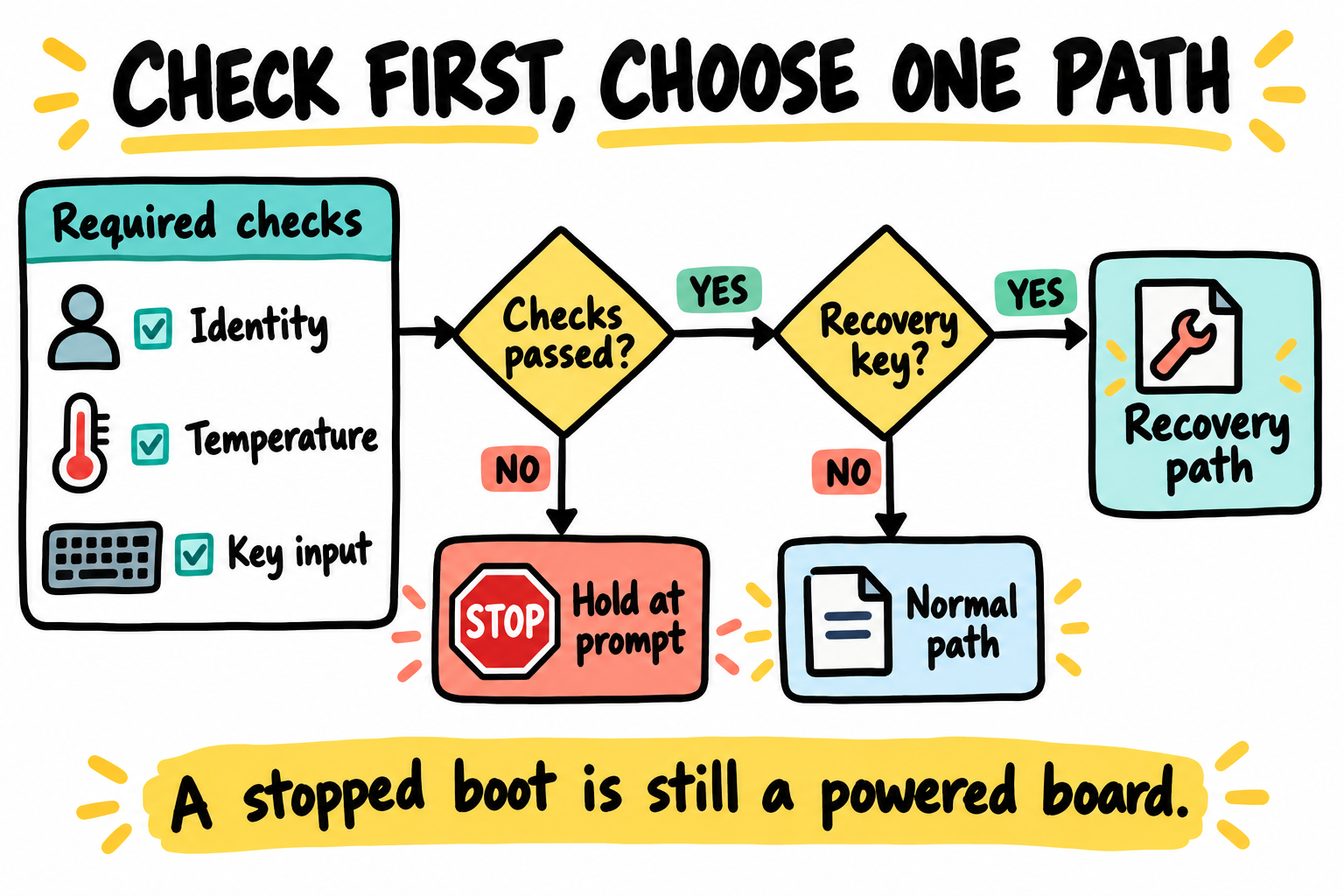
Open only one path after its prerequisites pass. This diagram shows the combined sensor/identity add-on policy developed across these chapters. A stock MINI uses KEY0 without those absent devices. It is not a hardware safety circuit. Holding at the prompt does not remove power.
24B.12 Key Notes
board_late_init()runs after environment import but before normal dispatch. A blocked-first hook prevents stale saved commands from opening the gate before required inputs are valid.The stock MINI input is KEY0 on UART1_CTS/GPIO1_IO18. The TMP102 is an optional add-on, so its mandatory temperature gate belongs only to a sensor-equipped hardware contract.
TMP102 comparison uses signed sixteenth-degree counts, preserving negative values and fractional thresholds. Transport errors and unsupported sensor modes are not valid samples.
GPIO lookup, claim, mux, polarity and release are separate responsibilities. Descriptor logical activity already includes active-low interpretation, while bounded stable samples define the example’s debounce policy.
Recovery and normal dispatch are exclusive choices. Changing
bootcmdinside a running script does not cancel commands that follow in that script.A late software hold leaves power applied and permits operator commands. It is neither ROM-time protection nor a security or thermal-shutdown boundary, and it requires no persistent environment or fuse changes.
24B.13 Pitfalls
Pointer width. Sensor register pointers and EEPROM addresses can have different widths.
Bus selection. A U-Boot sequence is not a Linux adapter number; muxes introduce child buses.
Unsigned temperature. Preserve signed counts for comparison and reporting.
Environment errors. Do not open the gate after a failed assignment.
Pin ownership. Direction changes on shared reset/power pins affect hardware immediately.
Gate bypass. Mutable environment and prompt access are not trusted boot policy.
Powered hold. A board at the prompt can continue to heat.
24B.14 Going deeper
GPIO descriptors and uclass: claims, polarity and release.
Board initialization and autoboot: detection before execution.
Environment API: volatile updates and return values.
Previous: Chapter 24A: Building i.MX6ULL U-Boot from nothing