Chapter 20: U-Boot SPL: the missing link
Chapter 19 left us with a large U-Boot image and a small question: how could the ROM load it into DDR before U-Boot’s C code had initialized that DDR?
For our MINI vendor configuration, the answer was the DCD. The ROM interpreted its register writes first. Another board can give that job to a small program instead. That program is SPL, the Secondary Program Loader.
SPL is an alternative boot stage, not a file missing from our MINI build. Knowing which route you have is more useful than memorizing a universal “ROM, SPL, U-Boot” diagram. We will read an actual SPL implementation, then compare its responsibilities with the MINI’s ROM-driven setup. The comparison uses another board’s source on the host. It does not replace our MINI firmware.
20.1 Why two stages
DDR cannot hold a useful stack or executable image until its controller, pads, clocks, and memory device have been configured. The startup program must therefore begin in memory that is already usable.
Two routes solve that dependency on this SoC family:
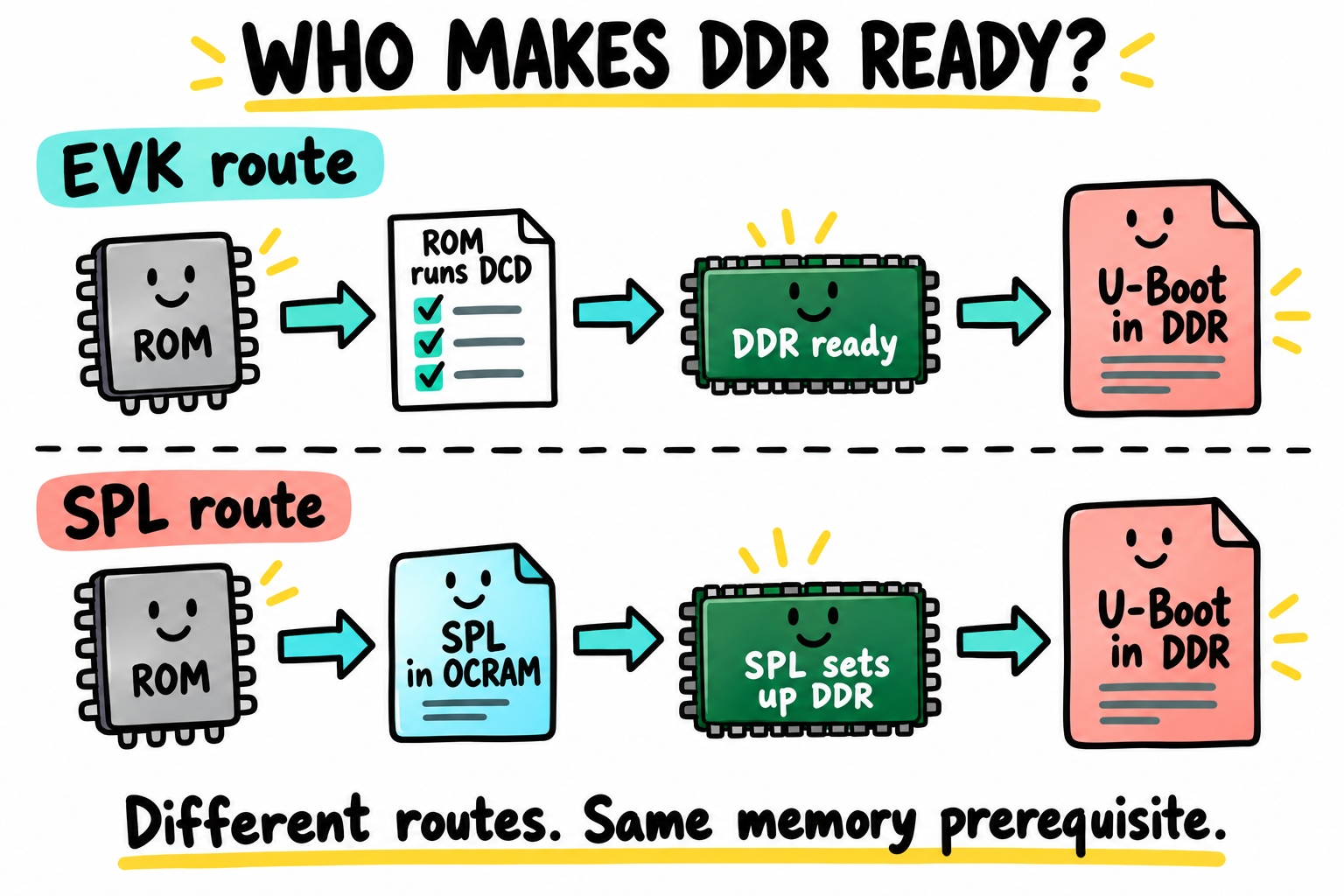
Our MINI uses the upper route too. The EVK label names another example of ROM-interpreted DDR setup, not the board we need to buy. The lower route assigns that work to SPL code.
Route |
Who prepares DDR? |
Where the first application code runs |
|---|---|---|
MINI ROM + DCD |
The Boot ROM executes the image’s DDR setup data |
Full U-Boot begins in DDR |
ROM + SPL |
A small executable runs its board-specific DDR setup |
SPL begins in internal RAM, then loads full U-Boot into DDR |
Both routes still need correct board-specific DDR values. Moving the writes from a DCD into C does not remove the electrical or calibration work from Chapter 14. It changes where that knowledge is expressed and how much software can run before the large image is loaded.
Some SPL configurations can select among memory arrangements, perform more complex initialization, authenticate a payload, or boot an OS directly. Those are configured features, not promises made by the name SPL.
20.2 What SPL is responsible for
For a typical i.MX6-family SPL loading full U-Boot, the responsibilities are:
Establish a usable CPU mode, early stack, and global-data area.
Prepare the clock and pad paths needed by its console, DDR, and boot medium.
Initialize the fitted DDR arrangement.
Initialize the selected SD, eMMC, SPI, or other loader path.
Read and interpret the configured payload format.
Place that payload at its load address and transfer control to its entry.
A console is often made available before DDR setup so that an early failure can be reported. The exact order belongs to the board implementation. Do not reorder the calls just to make them resemble a generic diagram.
Likewise, “SPL cannot use networking” is too broad. Some builds include it. The usual engineering question is whether a feature is needed before the larger runtime is available, and whether its memory and dependencies fit.
20.3 The size budget
The i.MX6ULL has 128 KiB of OCRAM. That physical capacity is not a promise that all 128 KiB are available to a loaded program. ROM activity, image placement, the early stack, global data, and any early allocation pool also need space. Use the selected image format, ROM constraints, configuration, and linker map together. Do not infer a free window by subtracting an approximate reservation quoted for another board.
For the reference SPL used below, CONFIG_SPL_MAX_SIZE is 0x10000, or
64 KiB. The Kconfig help describes this as the image limit excluding BSS.
That is different from a limit on text + data + bss + stack.
In this family, an SPL may place BSS in DDR and clear it only after DDR setup. The early code must not use that BSS while DDR is unavailable. Its OCRAM code and stack budget and its later DDR budget are separate checks.
Record these fields from the generated configuration rather than copying another build’s size report:
Field or file |
Check |
|---|---|
|
Where SPL code is linked |
|
Which loadable image limit the linker checks |
SPL stack selection |
Where the early stack begins and what lies below it |
|
Where BSS lives and when that memory becomes usable |
|
Actual linked ranges and reservations |
|
ELF section sizes and addresses |
|
The ROM-facing packaged file, including its header |
Not every feature has a one-to-one CONFIG_SPL_FOO switch. Dependencies,
shared framework code, and stage-specific defaults matter too. Inspect the
expanded configuration after changing a feature.
20.4 Where SPL lives in the source
Our MINI baseline has no SPL to inspect. For this comparison and the modern internals examples that follow, create a separate upstream v2026.04 study tree. Keep the vendor tree and its MINI image from Chapter 19 unchanged:
$ cd ~/imx6ull/src
$ git clone --branch v2026.04 https://source.denx.de/u-boot/u-boot.git u-boot
$ cd u-boot
$ git rev-parse HEAD
88dc2788777babfd6322fa655df549a019aa1e69
If that directory already exists, inspect its revision and preserve local changes instead of cloning over it. This fixed release gives Chapters 20-24J one set of modern APIs to discuss. Their C patches belong here, not in the 2016 vendor tree. Chapter 22 maps the MINI’s hardware into this newer framework.
We also need a full-U-Boot reference for Chapter 21’s map and command example:
$ . ~/imx6ull/scripts/env.sh
$ make O="$HOME/imx6ull/build/uboot-evk" mx6ull_14x14_evk_defconfig
$ make O="$HOME/imx6ull/build/uboot-evk" -j4
This is a host-side comparison build, not an image to flash to MINI. Its
host tools may need libgnutls28-dev in the Chapter 3 lab Ubuntu environment.
That dependency does not change either project-local Arm toolchain.
Now use a real SPL-enabled configuration. In this v2026.04 tree,
use pico-imx6ul_defconfig as a separate host-side reference. It describes
a TechNexion PICO i.MX6UL platform, not the i.MX6ULL EVK and not our MINI.
Do not flash its outputs to either board.
$ . ~/imx6ull/scripts/env.sh
$ cd ~/imx6ull/src/u-boot
$ make O="$HOME/imx6ull/build/uboot-pico-study" pico-imx6ul_defconfig
$ make O="$HOME/imx6ull/build/uboot-pico-study" -j4
$ arm-none-linux-gnueabihf-size \
    ~/imx6ull/build/uboot-pico-study/spl/u-boot-spl
The different O= directory keeps this configuration out of both the EVK study
build and the MINI vendor build.
The Arm-prefixed size program reads the target ELF on the host. It does not
execute it. Its BSS count is useful, but does not describe stack usage or all
packaging overhead. We are borrowing a source example, not changing the MINI’s
documented boot route.
Read these source files with the generated .config beside them:
Path |
Responsibility |
|---|---|
|
This board’s early setup, DDR data, and MMC setup |
|
Shared ARMv7 CPU startup |
|
Early C-runtime arrangements and stage-dependent paths |
|
SPL framework and boot-device selection |
|
MMC payload loading |
|
Shared MMDC configuration routines |
|
Stage limits, formats, and loader defaults |
An SPL file appears only when the build includes that stage. Looking for TI’s
MLO, or guessing an .imx filename, is not a way to repair a no-SPL EVK build.
20.5 Reading start.S
Open arch/arm/cpu/armv7/start.S, then follow its branch into _main in
arch/arm/lib/crt0.S. The names are familiar from Part II, but the framework
must accommodate more than our one experiment.
Startup work |
What to look for |
|---|---|
Preserve incoming boot information |
|
Select or respect CPU mode, mask IRQ/FIQ |
The CPSR manipulation and conditional mode check |
Establish architecture state |
|
Make early C calls possible |
Initial stack selection, alignment, and global-data reservation in |
Enter board setup |
The call to |
The generic mode check is not evidence that this board normally enters in HYP mode. The handoff policy depends on the ROM or preceding firmware and the selected platform. Similarly, masking IRQ and FIQ does not make bad memory accesses harmless.
Notice the explicit r9 global-data setup in crt0.S. A stack alone is not
the whole early environment. The framework gives early code a place to retain
state even before its normal runtime is ready.
In v2026.04, assembly and shared code use CONFIG_XPL_BUILD for these small
loader stages. Older excerpts may say CONFIG_SPL_BUILD. Read the pinned tree’s
conditions, not just a function with a familiar name.
20.6 board_init_f, the “before relocation” stage
The PICO implementation’s sequence can be summarized as:
clock gates
    -> architecture and board early setup
    -> timer
    -> preloader console
    -> board DDR configuration
    -> BSS clear
    -> SPL board_init_r
This is a reading map, not replacement code. Open the actual function to see the calls and the DDR data they use.
The order explains something important: this implementation clears BSS after DDR setup because its BSS location is in DDR. That region is not available for an early timeout counter merely because the C declaration compiled.
Also notice that this board’s board_init_f calls board_init_r directly.
Other SPL implementations return to crt0.S, which completes the stage’s
runtime setup. The chosen board path decides. A direct call is not a
universal rule that every function named board_init_f never returns.
Find the PICO DDR geometry and calibration structures, then follow the call
to mx6_dram_cfg. They are examples of how one supported board supplies data
to common MMDC code. They are not calibration results for our MINI.
20.7 board_init_r, the “after relocation” stage
Full U-Boot uses this name for its post-relocation runtime. SPL keeps the name for its later framework phase, even when its code has not relocated.
Follow board_init_r in common/spl/spl.c into boot-order selection, registered
loaders, and the selected image-loading function. The framework is not simply
a hard-coded call with BOOT_DEVICE_MMC1 on every board.
For the PICO raw-MMC reference, inspect
CONFIG_SYS_MMCSD_RAW_MODE_U_BOOT_SECTOR. The family default is 0x8A:
0x8A = 138 sectors
138 * 512 bytes = 70656 bytes = 69 KiB
That explains an offset you may have seen in other i.MX6 SPL instructions.
It does not change the MINI image placement in Chapter 19. The loader’s
expected payload format matters as well: a legacy u-boot.img, a FIT, and a
ROM-facing DCD image are not interchangeable just because they contain U-Boot.
The loader records a load address, entry address, and size in
struct spl_image_info. On success, the selected handoff enters that payload.
On failure, the configured boot order may try another supported loader or stop.
Find the actual error path before interpreting a later boot message.
20.8 Comparing SPL to your Ch 11 image-builder
Our Chapter 11 file included a leading pad, an IVT at file offset 0x400,
BootData, a header gap, and an OCRAM payload. U-Boot’s packaged SPL has its
own placement convention. Inspect the artifact rather than assuming that its
name implies the same leading pad.
$ xxd -l 32 ~/imx6ull/build/uboot-pico-study/SPL
$ ~/imx6ull/build/uboot-pico-study/tools/mkimage -l \
    ~/imx6ull/build/uboot-pico-study/SPL
For this packaged SPL, examine the IVT at file byte zero. Its entry and self
pointers refer to internal RAM rather than the DDR entry of the EVK image.
Use the image tool and selected configuration to interpret the remaining
fields. Do not substitute the entry from a full-U-Boot .imx dump.
The tool may print Mode: DCD for both files. In this implementation that
label distinguishes the non-plugin header mode, not proof that a DDR setup
table is present. The PICO wrapper selected by arch/arm/mach-imx/spl_sd.cfg
does not supply the EVK’s DDR writes. Check the actual DCD pointer and table
before deciding who initialized memory.
An OCRAM-loaded SPL does not need the ROM to initialize DDR just to load the SPL itself. Its own board code can do that afterward. A DDR-loaded full image does need DDR before it can execute, which is why the EVK supplies a DCD.
The meaningful comparison is the dependency, not an identical filename or an identical amount of padding:
Which memory must already work before the next instruction can be fetched?
20.9 The SPL-to-U-Boot handshake
spl_image_info is the SPL loader’s record. It tells the handoff where an image
was placed and where to enter it. It is not automatically an argument that full
U-Boot reads from the SPL’s old stack.
The payload also depends on established state:
Its code and required data must actually be present in usable memory.
Its load and entry addresses must agree with the selected format and build.
Memory writes must be visible to the instruction-fetch path when needed.
CPU mode, caches, MMU, and device state must satisfy the selected entry path.
The exact cache-maintenance and jump behavior belongs to the selected loader,
architecture, and configuration. Do not infer that every SPL automatically
performs cleanup_before_linux() before every possible handoff. Read the
selected jump_to_image_no_args implementation and any board override.
Some configurations provide additional handoff records through facilities such
as a blob list. Those are separate interfaces. For our reading example, trace
the normal full-U-Boot entry into crt0.S; it establishes its own runtime
instead of treating the preceding program’s stack as its permanent stack.
20.10 Key Notes
DCD and SPL solve the same early-memory dependency with different owners: ROM interprets a table, while SPL executes board-specific initialization code.
The PICO SPL and EVK full-U-Boot sources are comparison cases, not MINI firmware. Their payload formats and raw-MMC offsets do not replace Chapter 19’s layout.
A loadable-image size limit excludes other runtime consumers. OCRAM code, stack and early allocation, plus any later DDR-resident BSS, have separate lifetimes and budgets.
The PICO path clears its DDR-resident BSS only after DDR initialization. A compiled C variable is not usable before its backing memory exists.
board_init_fandboard_init_rnames do not impose universal return or relocation behavior. The selected board and stage determine the actual handoff.spl_image_inforecords placement and entry information. The next stage also depends on CPU, cache and memory state, not merely a function-pointer jump.
20.11 Pitfalls
Looking for SPL in every build. Check
CONFIG_SPLfirst. Our EVK does not use it, and a missing file there is expected.Treating 64 KiB as the whole runtime budget. The loadable image limit, BSS location, early stack, header, and allocation pool are different facts.
Accessing DDR-resident BSS before DDR setup. Successful compilation says nothing about whether that address is usable at that moment.
Copying another board’s DDR structures. They describe its memory and calibration, not a generic i.MX6UL/ULL memory device.
Using full-U-Boot DT assumptions for SPL. Stage filtering and available drivers determine what an SPL can bind and probe. Inspect the stage’s output.
Guessing handoff cleanup. Follow the actual path and its ownership rules. A function-pointer call does not by itself synchronize cached instructions.
20.12 Going deeper
Next we return to full U-Boot. Whether the ROM or an SPL made DDR usable, the large program still has to arrange its own stack, relocation, devices, and shell.