Chapter 24A: Building an i.MX6ULL teaching port from scratch
On an MCU, you can often reach main() by supplying a vector table, a linker script, and a few clock writes. Here the Boot ROM must first make external memory usable, load a much larger executable, and transfer control to it. U-Boot then builds its own runtime: a stack, global data, device discovery, relocation, and finally a command interpreter. A serial message at one stage does not prove that the later stages work.
Chapter 19’s first practical MINI build uses the official Alientek vendor source at commit edb7ca5ac4be2d978be60a2a12c61e0b6d1f7feb with mx6ull_alientek_emmc_defconfig. Keep that baseline for first board work. This optional chapter takes a deeper educational route on upstream U-Boot: keep the generic ARMv7 startup and frameworks, but give UART1, GPT1, and USDHC2 their own small register-level implementations. The silicon is not new to upstream U-Boot. Our new ARCH_IMX6ULL selection is a separate teaching route, not a replacement for the normal ARCH_MX6 port and not a qualified full-chip port.
The supplied listings build against upstream v2026.04, commit 88dc2788777babfd6322fa655df549a019aa1e69 and include the vendor-documented DDR initializer for the supplied 512 MiB eMMC core-board design. Section 24A.14 identifies its exact provenance, and section 24A.21 creates the actual ROM+DCD image without an omitted file. Source compilation and image inspection are verified checkpoints, not board-test results. No DDR calibration measured by us or successful boot of this custom port is claimed here.
This chapter follows one rule:
Each supplied new file is shown in full. For existing files, insertion fragments identify the manual edit location; they are not standalone
git applypatches. DDR constants come from a named vendor source, not from a guessed table. Framework code is named where it enters our boot path.
We reuse U-Boot’s architecture startup, driver model, MMC protocol state machine, block layer, and command shell. Our three small drivers make the peripheral boundary visible. We do not implement power management, all clock roots, security setup, or every silicon erratum. Treat those omissions as reasons to use the upstream platform for product work, not as proof that they are unnecessary.
24A.1 The exact hardware used in this chapter
A real low-level port cannot use a fictional chip. Register values that are “close enough” produce a silent board.
This chapter uses this exact target:
Item |
Value used here |
|---|---|
Board |
Point Atom MINI i.MX6ULL board |
CPU |
NXP i.MX6ULL, one Cortex-A7 core |
DDR |
Supplied core V2.0: one x16 512 MiB DDR3L |
First boot medium |
Removable SD card |
On-board storage to inspect later |
eMMC on USDHC2, eight wired data lines; begin in 1-bit legacy mode |
Console |
UART1 through the board’s built-in USB-to-TTL circuit |
Console settings |
115200 baud, 8 data bits, no parity, 1 stop bit |
U-Boot source |
Upstream U-Boot v2026.04 |
Cross compiler prefix |
|
ARCH_IMX6ULL is our new architecture symbol. We deliberately do not select ARCH_MX6 or link arch/arm/mach-imx/. In v2026.04, the standard mx6ull_14x14_evk_defconfig uses board/nxp/mx6ullevk/; it has a ROM+DCD image and no SPL. We inspect that source to check APIs and formats, but do not borrow its EVK DDR values as MINI board data.
The supplied core V2.0 and MINI baseboard V2.2 schematics, the vendor guide’s MINI applicability table, and its eMMC-core DDR description support this documented target. Compare them with the actual assembly before hardware work: the guide explicitly allows future DDR substitutions. Keep a hardware ledger with board revision, fitted DDR/eMMC markings, rails, BSP revision, inherited DDR clock, and calibration/test records. The complete source image can be built now, but its suitability for a particular physical assembly and its runtime stability remain hardware checks.
Values that must change on another board
Do not use this image unchanged on an i.MX6ULL board with a different DDR part or PCB layout.
Value |
Why it is board-specific |
|---|---|
DDR calibration registers |
They compensate for signal delay on this PCB and DDR layout. |
DDR geometry and timing |
They describe the fitted memory device. |
UART pads |
Another board may route UART1 to different pads. |
eMMC pads and bus width |
Another board may use USDHC1, a 4-bit bus, or no eMMC. |
Boot switches |
Their physical positions are board-specific. |
The SoC register addresses do not change between boards that use the same i.MX6ULL silicon.
24A.2 The complete first boot path
The i.MX6ULL has 128 KiB of OCRAM. A normal full U-Boot image does not fit there. We have two possible designs:
The Boot ROM loads a small SPL into OCRAM. SPL initializes DDR and then loads full U-Boot.
The Boot ROM reads a DCD table from the image header, performs the DDR register writes itself, and then loads full U-Boot directly into DDR.
We use the second design. The intended milestone is a U-Boot prompt after a qualified ROM+DCD load; adding SPL would introduce a different executable and load contract to debug.
SD card
  offset 0x00000400: i.MX image header, IVT, Boot Data, and DCD
  following bytes:   u-boot.bin
          |
          v
i.MX6ULL Boot ROM
  1. Finds the image at SD offset 0x400
  2. Copies the small header and DCD into internal memory
  3. Performs every DCD register write in order
  4. DDR is usable only if that board's DCD is correct
  5. Loads u-boot.bin to 0x87800000 in DDR
  6. Jumps to the entry address 0x87800000
          |
          v
Our IMX6ULL platform code
  1. Selects simple, known clock sources
  2. Initializes UART1 and prints an early marker
  3. Continues board_init_f: early DM/board marker, timer and console
  4. Declares the conditional DDR bank and reserves relocation space
          |
          v
Generic ARM handoff in crt0.S
  1. board_init_f returns; switch stack/global data to reserved DDR
  2. relocate_code copies/fixes the executable and resumes there
  3. Set final runtime state, clear BSS, and enter board_init_r
          |
          v
U-Boot after relocation
  1. Rebuilds driver-model state and the normal console
  2. Binds the USDHC2 host; card identification occurs when requested
  3. Shows the imx6ull=> prompt
There is no SPL in this design. The ROM executes the documented board-specific DCD before the first U-Boot instruction. dram_init() later reports a memory bank; it cannot repair an incorrect DCD because its own code is already running from DDR.
Memory map used by this port
Address or range |
Use |
|---|---|
|
128 KiB OCRAM used for the first stack and global data after ROM handoff |
|
Configured 512 MiB DDR bank for the documented core, subject to physical validation |
|
Linux boot-parameter address reported by the board code |
|
Default kernel or test-file load address |
|
Default Device Tree load address for Linux |
|
U-Boot link address, ROM load address, and first entry address |
CONFIG_TEXT_BASE and the mkimage -e argument must both be 0x87800000. If they differ, the ROM can load the bytes correctly and still jump to the wrong place.
OCRAM is 128 KiB, not the larger aliased address window above it. The ROM reserves parts of OCRAM while booting; the reference manual permits its use after normal boot handoff. This teaching port does not call back into the ROM. Its early stack and global data use OCRAM, while the executable and appended DTB already reside in DDR. Relocation later reserves U-Boot, stack, malloc, and other runtime data near the top of the reported bank. The load addresses in this table are conventions, not ownership reservations.
24A.3 What we write, edit, and reuse
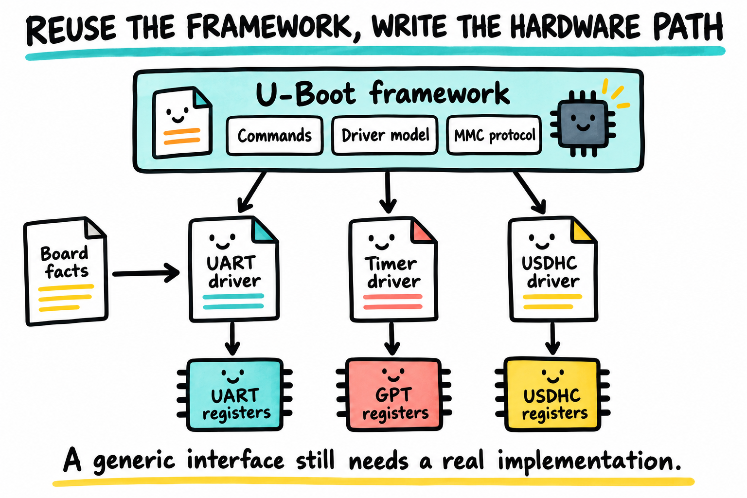
Reuse the framework, but make the hardware boundary explicit. A common interface cannot talk to a new controller until a driver implements its register-level contract. The icons represent software layers, not physical board wiring.
Create these files:
arch/arm/mach-imx6ull/
|-- Kconfig
|-- Makefile
|-- clock.c
|-- cpu.c
|-- early_uart.c
`-- include/mach/
    |-- clock.h
    |-- hardware.h
    `-- uart.h

board/point-atom/imx6ull-mini/
|-- Kconfig
|-- MAINTAINERS
|-- Makefile
|-- board.c
`-- imximage.cfg

arch/arm/dts/
|-- imx6ull-from-scratch.dtsi
|-- imx6ull-point-atom-mini-from-scratch.dts
`-- imx6ull-point-atom-mini-from-scratch-u-boot.dtsi

drivers/serial/serial_imx6ull.c
drivers/timer/imx6ull_gpt_timer.c
drivers/mmc/imx6ull_usdhc.c
configs/imx6ull_point_atom_mini_defconfig
include/configs/imx6ull_point_atom_mini.h
Edit these existing files:
arch/arm/Kconfig
arch/arm/Makefile
arch/arm/dts/Makefile
drivers/serial/Kconfig
drivers/serial/Makefile
drivers/timer/Kconfig
drivers/timer/Makefile
drivers/mmc/Kconfig
drivers/mmc/Makefile
Reuse these existing U-Boot files without changing their C code:
Existing file |
What we reuse |
|---|---|
|
CPU entry/state setup, early stack/global data, and entry into |
|
Copies U-Boot to its final DDR location and fixes addresses |
|
Initialization before relocation |
|
Initialization after relocation and command loop |
|
The hardware-independent MMC and eMMC command sequence |
|
Connects our host driver to U-Boot’s MMC uclass |
|
Exposes the discovered eMMC as a block device |
|
Builds the i.MX IVT, Boot Data, and DCD image header |
Before relocation, board_init_f() builds enough runtime state to size DDR and reserve the destination. crt0.S and relocate.S move to that destination; board_init_r() runs with writable globals and the full runtime. Driver model (DM) matches each Device Tree node to a driver and allocates its per-device data. A uclass is the common interface, such as serial or MMC, that the rest of U-Boot calls. This is the point where the MCU habit of calling one peripheral function directly becomes a framework callback contract.
24A.4 Start from a clean U-Boot tree
Use a separate checkout for this alternative port. Keep Chapter 21’s command-example branch and Chapter 22’s normal-MX6 board work in their existing checkout; do not check that edited tree back to the tag to make a version check pass. Run these commands on the Linux build host:
$ . ~/imx6ull/scripts/env.sh
$ cd ~/imx6ull/src
$ git clone --branch v2026.04 https://source.denx.de/u-boot/u-boot.git u-boot-24a
$ cd u-boot-24a
$ UBOOT_BASE=88dc2788777babfd6322fa655df549a019aa1e69
$ git describe --tags --exact-match HEAD
$ test "$(git rev-parse --verify 'v2026.04^{commit}')" = "$UBOOT_BASE"
$ test "$(git rev-parse HEAD)" = "$UBOOT_BASE"
$ git rev-parse HEAD
$ git switch -c imx6ull-from-scratch
Confirm the compiler before editing anything:
$ arm-none-linux-gnueabihf-gcc --version
$ make --version
$ dtc --version
Before making custom commits, the tag’s resolved commit and HEAD must both match the pin above. Stop on any failed check. If u-boot-24a already exists, inspect its history and local changes instead of overwriting it. Once custom commits exist, HEAD is expected to differ and an exact-tag query on it is no longer the right check; section 24A.20 checks the pinned base’s ancestry instead. Neither check says that uncommitted files are unchanged, so always inspect git status --short as well.
The compiler must be Chapter 3’s project-local Linux-target Arm GNU 13.2.Rel1 compiler, with prefix arm-none-linux-gnueabihf-. Preserve the separate arm-none-eabi- installation used for bare-metal work. Source the environment in each build shell; do not edit .bashrc, system paths, or global Git configuration. Native GCC builds host utilities, but cannot replace the ARM cross compiler for the target executable.
Use Chapter 19’s host build dependencies as well: Make, native GCC, Bison, Flex, M4, bc, and the host development libraries required by U-Boot’s image tools. U-Boot builds its own DTC. The standalone dtc check is useful for inspecting trees, but does not select a target compiler.
Create the directories:
$ mkdir -p arch/arm/mach-imx6ull/include/mach
$ mkdir -p board/point-atom/imx6ull-mini
The other parent directories already exist in U-Boot.
24A.5 Build a hardware ledger before writing C
The table below is the bridge from the reference manual and Part II into U-Boot.
Hardware |
Address |
Facts used by our code |
|---|---|---|
OCRAM |
|
128 KiB |
DDR |
|
512 MiB only after the qualified DCD and geometry agree |
UART1 |
|
i.MX UART register layout |
GPT1 |
|
32-bit up-counter with a 24 MHz source |
WDOG1 |
|
Used by |
CCM |
|
Clock selectors, dividers, and gates |
IOMUXC |
|
Pad mux, pad electrical control, and input daisy selection |
MMDC |
|
DDR controller |
USDHC2 |
|
eMMC host controller |
The first visible code uses these UART1 registers:
Register |
Offset |
Purpose |
|---|---|---|
|
|
Received byte and receive status |
|
|
Byte to transmit |
|
|
Main UART enable |
|
|
Reset, TX, RX, word length, and flow-control settings |
|
|
RX input path setting |
|
|
Additional control settings |
|
|
FIFO thresholds and reference-clock divider |
|
|
Transmit-complete and receive-ready status |
|
|
Baud-rate numerator |
|
|
Baud-rate denominator |
|
|
FIFO empty and full status |
For first bring-up, arch_cpu_init() selects the 24 MHz oscillator as the UART root clock. This is slower than the 80 MHz PLL-derived clock used in Chapter 12, but it removes a PLL dependency. The baud-rate registers are calculated from the actual selected rate.
24A.6 Connect the new platform to the ARM build
Edit arch/arm/Kconfig
Search for config ARCH_KIRKWOOD. Insert this entry immediately above it, inside the same ARM platform choice:
+config ARCH_IMX6ULL
+	bool "Learning i.MX6ULL platform"
+	select CPU_V7A
+	select SUPPORT_OF_CONTROL
+	select SKIP_LOWLEVEL_INIT_ONLY
+	help
+	  Build the from-scratch IMX6ULL teaching port for the Point Atom
+	  MINI board. This deliberately does not use arch/arm/mach-imx.
Near the bottom of the same file, insert our source line after the HiSTB line:
 source "arch/arm/mach-histb/Kconfig"
+source "arch/arm/mach-imx6ull/Kconfig"
 source "arch/arm/mach-integrator/Kconfig"
The two changes do different jobs:
Change |
Effect |
|---|---|
|
Creates the platform option and says that the CPU implements ARMv7-A. |
Machine Kconfig source line |
Lets Kconfig read our board target and board directory settings. |
CPU_V7A makes U-Boot compile the generic Cortex-A7-compatible ARMv7 code. We do not write a reset vector.
SKIP_LOWLEVEL_INIT_ONLY skips the generic low-level platform hook because ROM+DCD already supplied DDR. Unlike SKIP_LOWLEVEL_INIT, it retains cpu_init_cp15(): the generic entry invalidates TLB/instruction state and disables the MMU and data cache before entering this runtime. The image assumes the normal ROM handoff, not an arbitrary jump from another firmware with dirty data caches. The two cache-off defconfig options also prevent later cache enabling. They do not, by themselves, clean an unknown predecessor’s dirty cache.
Edit arch/arm/Makefile
Add one line to the sorted machine list:
 machine-$(CONFIG_ARCH_HISTB)          += histb
+machine-$(CONFIG_ARCH_IMX6ULL)        += imx6ull
 machine-$(CONFIG_ARCH_IPQ40XX)        += ipq40xx
When CONFIG_ARCH_IMX6ULL=y, this line adds arch/arm/mach-imx6ull/ to the build and adds its include/ directory to the compiler’s header search path.
Create arch/arm/mach-imx6ull/Kconfig
if ARCH_IMX6ULL

config TARGET_IMX6ULL_POINT_ATOM_MINI
	bool "Point Atom MINI with 512 MiB DDR3L"
	select BOARD_EARLY_INIT_F
	help
	  Build U-Boot for the Point Atom MINI i.MX6ULL board. The first
	  image boots from SD and accesses the on-board eMMC through USDHC2.

source "board/point-atom/imx6ull-mini/Kconfig"

endif
There is only one board today, so this is a bool, not a choice. A future second board can turn this section into a choice.
BOARD_EARLY_INIT_F tells common U-Boot that our board supplies board_early_init_f(). That hook runs before relocation. We use it only for an early progress message.
Create arch/arm/mach-imx6ull/Makefile
# SPDX-License-Identifier: GPL-2.0+

obj-y += clock.o
obj-y += cpu.o
obj-y += early_uart.o
Each object is built into full U-Boot whenever ARCH_IMX6ULL is selected.
24A.7 Define the hardware addresses
Create arch/arm/mach-imx6ull/include/mach/hardware.h:
/* SPDX-License-Identifier: GPL-2.0+ */
#ifndef __IMX6ULL_HARDWARE_H
#define __IMX6ULL_HARDWARE_H

#include <linux/sizes.h>

#define IMX6ULL_OCRAM_BASE             0x00900000UL
#define IMX6ULL_OCRAM_SIZE             SZ_128K

#define IMX6ULL_DDR_BASE               0x80000000UL
#define IMX6ULL_DDR_SIZE               SZ_512M

#define IMX6ULL_UART1_BASE             0x02020000UL
#define IMX6ULL_GPT1_BASE              0x02098000UL
#define IMX6ULL_WDOG1_BASE             0x020BC000UL
#define IMX6ULL_WDOG2_BASE             0x020C0000UL
#define IMX6ULL_WDOG3_BASE             0x021E4000UL
#define IMX6ULL_SRC_SCR                0x020D8000UL
#define IMX6ULL_CCM_BASE               0x020C4000UL
#define IMX6ULL_IOMUXC_BASE            0x020E0000UL
#define IMX6ULL_MMDC_BASE              0x021B0000UL
#define IMX6ULL_USDHC2_BASE            0x02194000UL

#define IMX6ULL_CCM_CSCMR1             0x020C401CUL
#define IMX6ULL_CCM_CSCDR1             0x020C4024UL
#define IMX6ULL_CCM_CCGR1              0x020C406CUL
#define IMX6ULL_CCM_CCGR3              0x020C4074UL
#define IMX6ULL_CCM_CCGR5              0x020C407CUL
#define IMX6ULL_CCM_CCGR6              0x020C4080UL

#define IMX6ULL_ANATOP_PLL2            0x020C8030UL
#define IMX6ULL_ANATOP_PFD_528         0x020C8100UL

#define IMX6ULL_UART1_TX_MUX            0x020E0084UL
#define IMX6ULL_UART1_RX_MUX            0x020E0088UL
#define IMX6ULL_UART1_TX_PAD            0x020E0310UL
#define IMX6ULL_UART1_RX_PAD            0x020E0314UL
#define IMX6ULL_UART1_RX_SELECT         0x020E0624UL

#endif
This header contains addresses and sizes only. It does not initialize anything. The UL suffix makes each constant an unsigned long, which avoids signed-address warnings on 32-bit ARM.
24A.8 Write the clock code
Create arch/arm/mach-imx6ull/include/mach/clock.h:
/* SPDX-License-Identifier: GPL-2.0+ */
#ifndef __IMX6ULL_CLOCK_H
#define __IMX6ULL_CLOCK_H

#include <linux/types.h>

void imx6ull_clock_init(void);
u32 imx6ull_get_uart_clock(void);
u32 imx6ull_get_usdhc2_clock(void);

#endif
Both drivers written in this chapter call these functions directly. There is no existing i.MX clock API between our code and the registers.
Create arch/arm/mach-imx6ull/clock.c:
// SPDX-License-Identifier: GPL-2.0+
#include <asm/io.h>
#include <asm/arch/clock.h>
#include <asm/arch/hardware.h>
#include <linux/bitops.h>

#define CCM_CSCDR1_UART_CLK_PODF_MASK   0x3f
#define CCM_CSCDR1_UART_CLK_SEL         BIT(6)

#define CCM_CSCMR1_USDHC2_CLK_SEL       BIT(17)
#define CCM_CSCDR1_USDHC2_PODF_MASK     (0x7 << 16)
#define CCM_CSCDR1_USDHC2_PODF_DIV2     (0x1 << 16)

#define CCM_CCGR1_GPT1_MASK             ((0x3 << 20) | (0x3 << 22))
#define CCM_CCGR3_WDOG1_MASK            (0x3 << 16)
#define CCM_CCGR5_UART1_MASK            (0x3 << 24)
#define CCM_CCGR6_USDHC2_MASK           (0x3 << 4)

#define OSCILLATOR_HZ                    24000000U
#define PLL2_DIV_SELECT                 BIT(0)
#define PLL2_POWERDOWN                  BIT(12)
#define PLL2_ENABLE                     BIT(13)
#define PLL2_BYPASS                     BIT(16)
#define PLL2_LOCK                       BIT(31)
#define PFD2_FRAC_SHIFT                 16
#define PFD2_FRAC_MASK                  (0x3f << PFD2_FRAC_SHIFT)
#define PFD2_CLKGATE                    BIT(23)

void imx6ull_clock_init(void)
{
	/* UART root = 24 MHz oscillator, divider = 1. */
	clrsetbits_le32((void *)IMX6ULL_CCM_CSCDR1,
			  CCM_CSCDR1_UART_CLK_SEL |
			  CCM_CSCDR1_UART_CLK_PODF_MASK,
			  CCM_CSCDR1_UART_CLK_SEL);

	/* Stop this unused host while switching its root, not the DDR PLL. */
	clrbits_le32((void *)IMX6ULL_CCM_CCGR6, CCM_CCGR6_USDHC2_MASK);
	/* USDHC2 root = existing PLL2 PFD2, divided by 2. */
	clrbits_le32((void *)IMX6ULL_CCM_CSCMR1,
		     CCM_CSCMR1_USDHC2_CLK_SEL);
	clrsetbits_le32((void *)IMX6ULL_CCM_CSCDR1,
			  CCM_CSCDR1_USDHC2_PODF_MASK,
			  CCM_CSCDR1_USDHC2_PODF_DIV2);

	/* Value 3 in a CCGR field enables the clock in every run mode. */
	setbits_le32((void *)IMX6ULL_CCM_CCGR1, CCM_CCGR1_GPT1_MASK);
	setbits_le32((void *)IMX6ULL_CCM_CCGR3, CCM_CCGR3_WDOG1_MASK);
	setbits_le32((void *)IMX6ULL_CCM_CCGR5, CCM_CCGR5_UART1_MASK);
	setbits_le32((void *)IMX6ULL_CCM_CCGR6, CCM_CCGR6_USDHC2_MASK);
}

u32 imx6ull_get_uart_clock(void)
{
	u32 cscdr1 = readl((void *)IMX6ULL_CCM_CSCDR1);
	u32 divider = (cscdr1 & CCM_CSCDR1_UART_CLK_PODF_MASK) + 1;
	if (!(cscdr1 & CCM_CSCDR1_UART_CLK_SEL))
		return 0; /* This port only decodes the oscillator path. */
	return OSCILLATOR_HZ / divider;
}

u32 imx6ull_get_usdhc2_clock(void)
{
	u32 pll2_control;
	u32 pfd_register;
	u32 pll2_rate;
	u32 pfd2_fraction;
	u32 usdhc2_divider;
	u32 cscdr1;

	pll2_control = readl((void *)IMX6ULL_ANATOP_PLL2);
	if (!(pll2_control & PLL2_LOCK) || !(pll2_control & PLL2_ENABLE) ||
	    (pll2_control & (PLL2_POWERDOWN | PLL2_BYPASS)))
		return 0;
	pll2_rate = OSCILLATOR_HZ *
		    (20 + ((pll2_control & PLL2_DIV_SELECT) << 1));

	pfd_register = readl((void *)IMX6ULL_ANATOP_PFD_528);
	pfd2_fraction = (pfd_register & PFD2_FRAC_MASK) >>
			PFD2_FRAC_SHIFT;
	if ((pfd_register & PFD2_CLKGATE) ||
	    pfd2_fraction < 12 || pfd2_fraction > 35)
		return 0;

	cscdr1 = readl((void *)IMX6ULL_CCM_CSCDR1);
	if (readl((void *)IMX6ULL_CCM_CSCMR1) & CCM_CSCMR1_USDHC2_CLK_SEL)
		return 0; /* PFD0 is outside this port's supported clock path. */
	usdhc2_divider = ((cscdr1 >> 16) & 0x7) + 1;

	return ((u64)pll2_rate * 18 / pfd2_fraction) / usdhc2_divider;
}
The UART calculation deliberately accepts only the oscillator path we selected. It does not guess an 80 MHz rate when a register says otherwise. GPT1 needs both its bus and serial gates enabled; setting only the bus gate can leave register access working while the counter does not advance.
USDHC2 uses an inherited PLL2/PFD2 path. We do not retune or power-cycle it: PLL2 also participates in the memory clock tree, and this code executes from DDR. The getter checks lock, enable, bypass, powerdown, PFD gate/fraction, and root selection. An unsupported state produces zero and the host probe fails. A successful ROM SD load alone does not prove every later USDHC2 clock assumption. With PLL2 at 528 MHz, fraction 24, and divider two, the calculation is 198 MHz. The host then chooses divisors that do not exceed the requested card clock. Record the inherited register state during later hardware qualification.
24A.9 Expose the early UART code
Create arch/arm/mach-imx6ull/include/mach/uart.h:
/* SPDX-License-Identifier: GPL-2.0+ */
#ifndef __IMX6ULL_UART_H
#define __IMX6ULL_UART_H

#include <linux/types.h>

struct imx6ull_uart {
	u32 rxd;
	u32 reserved0[15];
	u32 txd;
	u32 reserved1[15];
	u32 cr1;
	u32 cr2;
	u32 cr3;
	u32 cr4;
	u32 fcr;
	u32 sr1;
	u32 sr2;
	u32 esc;
	u32 tim;
	u32 bir;
	u32 bmr;
	u32 brc;
	u32 onems;
	u32 ts;
};

int imx6ull_uart_hw_init(struct imx6ull_uart *uart, u32 clock,
			  u32 baudrate);
void imx6ull_early_uart_putc(char ch);
void imx6ull_early_uart_puts(const char *text);

#endif
The reserved arrays are not unused memory. They preserve the gaps in the hardware register map. For example, txd must land at offset 0x40, not directly after rxd at offset 0x04.
Create arch/arm/mach-imx6ull/early_uart.c:
// SPDX-License-Identifier: GPL-2.0+
#include <asm/io.h>
#include <asm/arch/hardware.h>
#include <asm/arch/uart.h>
#include <errno.h>
#include <linux/bitops.h>

#define UCR1_UARTEN                    BIT(0)

#define UCR2_SRST                      BIT(0)
#define UCR2_RXEN                      BIT(1)
#define UCR2_TXEN                      BIT(2)
#define UCR2_WS                        BIT(5)
#define UCR2_IRTS                      BIT(14)

#define UCR3_RXDMUXSEL                 BIT(2)
#define UCR3_ADNIMP                    BIT(7)

#define UFCR_RFDIV_DIV2                (4 << 7)
#define UFCR_TXTL_2                    (2 << 10)
#define UFCR_RXTL_1                    1

#define UTS_TXFULL                     BIT(4)
#define USR2_TXDC                      BIT(3)

int imx6ull_uart_hw_init(struct imx6ull_uart *uart, u32 clock,
			  u32 baudrate)
{
	u32 divisor;
	u32 budget = 100000;

	if (!clock || !baudrate || baudrate > clock / 2)
		return -EINVAL;
	divisor = (clock / 2 + baudrate / 2) / baudrate;
	if (!divisor || divisor > 65536)
		return -EINVAL;

	writel(0, &uart->cr1);
	writel(0, &uart->cr2);

	/* No timer exists yet: this is a finite poll budget, not a duration. */
	while (!(readl(&uart->cr2) & UCR2_SRST)) {
		if (!--budget)
			return -ETIMEDOUT;
	}

	writel(0x704 | UCR3_ADNIMP | UCR3_RXDMUXSEL, &uart->cr3);
	writel(0x8000, &uart->cr4);
	writel(0x2b, &uart->esc);
	writel(0, &uart->tim);
	writel(0, &uart->ts);

	writel(UFCR_RFDIV_DIV2 | UFCR_TXTL_2 | UFCR_RXTL_1,
	       &uart->fcr);
	writel(0xf, &uart->bir);
	writel(divisor - 1, &uart->bmr);

	writel(UCR2_WS | UCR2_IRTS | UCR2_RXEN | UCR2_TXEN | UCR2_SRST,
	       &uart->cr2);
	setbits_le32(&uart->cr3, UCR3_RXDMUXSEL);
	writel(UCR1_UARTEN, &uart->cr1);
	return 0;
}

void imx6ull_early_uart_putc(char ch)
{
	struct imx6ull_uart *uart =
		(struct imx6ull_uart *)IMX6ULL_UART1_BASE;
	u32 budget = 100000;

	while (readl(&uart->ts) & UTS_TXFULL) {
		if (!--budget)
			return; /* Missing marker is a failure, not permission to continue. */
	}

	writel(ch, &uart->txd);
}

void imx6ull_early_uart_puts(const char *text)
{
	struct imx6ull_uart *uart =
		(struct imx6ull_uart *)IMX6ULL_UART1_BASE;
	u32 budget = 100000;

	while (*text) {
		if (*text == '\n')
			imx6ull_early_uart_putc('\r');
		imx6ull_early_uart_putc(*text++);
	}
	/* Complete the marker before DM can reset the same UART's FIFO. */
	while (!(readl(&uart->sr2) & USR2_TXDC)) {
		if (!--budget)
			return;
	}
}
This is the bare-metal UART code. U-Boot’s console is not running when it prints the first marker. The function writes directly to UART1 in the same way as Chapter 12.
The baud formula used by this UART is:
baud = reference_clock / 16 * (UBIR + 1) / (UBMR + 1)
UFCR divides the 24 MHz input by two. UBIR is 15, so (UBIR + 1) cancels the /16. Round 12000000 / 115200 to 104, then program UBMR = 104 - 1 = 103. The resulting rate is about 115385 baud. Forgetting the minus one programs a different divider, not merely a different representation. UART reset deasserts after module-clock cycles; the early bounded loop cannot promise a millisecond timeout before GPT exists. Early putc() waits for FIFO space, then puts() drains the marker with a bounded transmit-complete check before the later DM initialization can reset the FIFO. DM setbrg() and probe() propagate initialization failures.
24A.10 Write the SoC entry hooks
Create arch/arm/mach-imx6ull/cpu.c:
// SPDX-License-Identifier: GPL-2.0+
#include <asm/io.h>
#include <asm/arch/clock.h>
#include <asm/arch/hardware.h>
#include <asm/arch/uart.h>
#include <init.h>
#include <linux/bitops.h>
#include <linux/types.h>
#include <stdio.h>

#define WDOG_WCR_WDE                    BIT(2)
#define WDOG_WCR_WDA                    BIT(5)

struct imx6ull_watchdog_regs {
	u16 wcr;
	u16 wsr;
	u16 wrsr;
};

int arch_cpu_init(void)
{
	struct imx6ull_uart *uart =
		(struct imx6ull_uart *)IMX6ULL_UART1_BASE;
	int ret;

	imx6ull_clock_init();
	/* WMCR.PDE is separate from the normal watchdog-enable bit. */
	writew(0, (void *)(IMX6ULL_WDOG1_BASE + 0x08));
	writew(0, (void *)(IMX6ULL_WDOG2_BASE + 0x08));
	writew(0, (void *)(IMX6ULL_WDOG3_BASE + 0x08));
	/* Use cold reset, matching the normal ROM+DCD re-entry contract. */
	clrbits_le32((void *)IMX6ULL_SRC_SCR, BIT(0));
	ret = imx6ull_uart_hw_init(uart, imx6ull_get_uart_clock(), 115200);
	if (ret)
		return ret;
	imx6ull_early_uart_puts("\n[imx6ull] arch_cpu_init reached\n");

	return 0;
}

int print_cpuinfo(void)
{
	puts("CPU:   NXP i.MX6ULL, ARM Cortex-A7\n");
	return 0;
}

void reset_cpu(void)
{
	struct imx6ull_watchdog_regs *wdog =
		(struct imx6ull_watchdog_regs *)IMX6ULL_WDOG1_BASE;
	/* WCR.SRS is active low; leave WDA high for an internal reset. */
	u16 value = WDOG_WCR_WDE | WDOG_WCR_WDA;

	/* Three writes are required by i.MX6 erratum ERR004346. */
	writew(value, &wdog->wcr);
	writew(value, &wdog->wcr);
	writew(value, &wdog->wcr);

	while (1)
		;
}
Common U-Boot calls arch_cpu_init() from common/board_f.c before relocation. If the terminal shows the marker and then stops, we know all of these things already worked:
The Boot ROM found our image.
The IVT entry address was valid.
The DCD completed well enough for the ROM to load U-Boot into DDR.
Generic ARMv7 startup reached C code.
The stack is usable.
The CCM and UART register addresses are correct.
The board’s integrated USB-to-TTL connection is working.
That line proves a limited executable path, not all 512 MiB of DDR. It can appear despite marginal timing or address aliasing elsewhere in the bank. The reset routine uses a 16-bit register access and the ERR004346 repeated-write workaround; SRS=0 asserts the system reset, whereas SRS=1 does nothing. Its clock gate is enabled explicitly. The early hook clears the three watchdogs’ separate power-down enable bits, with their bus clocks available under this image’s broad DCD gating policy, and chooses cold-reset routing through SRC. It does not disable an already enabled normal watchdog: this first ROM entry assumes no inherited active normal watchdog that needs servicing. A chainloaded image would need a different audited handoff. Reset routing and repeated board power-cycle behavior remain hardware checks.
24A.11 Add the board directory
The register layout belongs to the SoC. The oscillator, inherited clock state, UART wiring, and reset assumptions still belong to a boot contract. The board files now add a conditional DDR bank and the two early checkpoints.
Create board/point-atom/imx6ull-mini/Kconfig
if TARGET_IMX6ULL_POINT_ATOM_MINI

config SYS_BOARD
	default "imx6ull-mini"

config SYS_VENDOR
	default "point-atom"

config SYS_SOC
	default "imx6ull"

config SYS_CONFIG_NAME
	default "imx6ull_point_atom_mini"

endif
These strings tell the build system where the board objects and legacy configuration header live:
Setting |
Result |
|---|---|
|
First part of |
|
Last part of |
|
Includes |
|
Gives tools and generated configuration a readable SoC name |
Create board/point-atom/imx6ull-mini/Makefile
# SPDX-License-Identifier: GPL-2.0+

obj-y += board.o
Create board/point-atom/imx6ull-mini/board.c
// SPDX-License-Identifier: GPL-2.0+
#include <asm/global_data.h>
#include <asm/arch/hardware.h>
#include <asm/arch/uart.h>
#include <linux/sizes.h>
#include <stdio.h>

DECLARE_GLOBAL_DATA_PTR;

int board_early_init_f(void)
{
	imx6ull_early_uart_puts("[imx6ull] board_early_init_f reached\n");
	return 0;
}

int dram_init(void)
{
	gd->ram_size = IMX6ULL_DDR_SIZE;
	return 0;
}

int dram_init_banksize(void)
{
	gd->bd->bi_dram[0].start = IMX6ULL_DDR_BASE;
	gd->bd->bi_dram[0].size = IMX6ULL_DDR_SIZE;
	return 0;
}

int board_init(void)
{
	gd->bd->bi_boot_params = IMX6ULL_DDR_BASE + 0x100;
	return 0;
}

int checkboard(void)
{
	puts("Board: Point Atom MINI, IMX6ULL teaching port\n");
	return 0;
}
dram_init() does not initialize or probe DDR. It assigns the bank size assumed by this teaching configuration. A printed 512 MiB line therefore proves only that the assignment ran. Use this configuration only after the fitted geometry, DCD, and full-bank validation agree with that size; otherwise change IMX6ULL_DDR_SIZE and the DTS memory node together.
dram_init_banksize() fills bank 0 in the board-information structure. Linux and U-Boot commands use this bank description later.
Create board/point-atom/imx6ull-mini/MAINTAINERS
IMX6ULL POINT ATOM MINI
M:      Your Name <you@example.com>
S:      Maintained
F:      arch/arm/dts/imx6ull-from-scratch.dtsi
F:      arch/arm/dts/imx6ull-point-atom-mini-from-scratch*
F:      arch/arm/mach-imx6ull/
F:      board/point-atom/imx6ull-mini/
F:      configs/imx6ull_point_atom_mini_defconfig
F:      drivers/mmc/imx6ull_usdhc.c
F:      drivers/serial/serial_imx6ull.c
F:      drivers/timer/imx6ull_gpt_timer.c
F:      include/configs/imx6ull_point_atom_mini.h
Replace the name and email before sending a real patch. MAINTAINERS tells get_maintainer.pl who owns these files. It does not affect the binary.
24A.12 Turn the UART code into a U-Boot driver
The early UART proves the hardware works. U-Boot’s command shell cannot call that private print function directly. The serial uclass expects a driver with putc, getc, pending, and setbrg operations.
Create drivers/serial/serial_imx6ull.c:
// SPDX-License-Identifier: GPL-2.0+
#include <dm.h>
#include <errno.h>
#include <serial.h>
#include <asm/io.h>
#include <asm/arch/clock.h>
#include <asm/arch/uart.h>
#include <linux/bitops.h>

#define URXD_RX_DATA                    0xff
#define USR2_TXDC                       BIT(3)
#define USR2_RDR                        BIT(0)
#define UTS_RXEMPTY                     BIT(5)
#define UTS_TXFULL                      BIT(4)

struct imx6ull_serial_plat {
	struct imx6ull_uart *uart;
};

static int imx6ull_serial_setbrg(struct udevice *dev, int baudrate)
{
	struct imx6ull_serial_plat *plat = dev_get_plat(dev);

	return imx6ull_uart_hw_init(plat->uart, imx6ull_get_uart_clock(), baudrate);
}

static int imx6ull_serial_probe(struct udevice *dev)
{
	struct imx6ull_serial_plat *plat = dev_get_plat(dev);

	return imx6ull_uart_hw_init(plat->uart, imx6ull_get_uart_clock(), 115200);
}

static int imx6ull_serial_putc(struct udevice *dev, const char ch)
{
	struct imx6ull_serial_plat *plat = dev_get_plat(dev);

	if (readl(&plat->uart->ts) & UTS_TXFULL)
		return -EAGAIN;

	writel(ch, &plat->uart->txd);
	return 0;
}

static int imx6ull_serial_getc(struct udevice *dev)
{
	struct imx6ull_serial_plat *plat = dev_get_plat(dev);

	if (readl(&plat->uart->ts) & UTS_RXEMPTY)
		return -EAGAIN;

	return readl(&plat->uart->rxd) & URXD_RX_DATA;
}

static int imx6ull_serial_pending(struct udevice *dev, bool input)
{
	struct imx6ull_serial_plat *plat = dev_get_plat(dev);
	u32 sr2 = readl(&plat->uart->sr2);

	if (input)
		return !!(sr2 & USR2_RDR);

	return !(sr2 & USR2_TXDC);
}

static int imx6ull_serial_of_to_plat(struct udevice *dev)
{
	struct imx6ull_serial_plat *plat = dev_get_plat(dev);
	fdt_addr_t address = dev_read_addr(dev);

	if (address == FDT_ADDR_T_NONE)
		return -EINVAL;

	plat->uart = (struct imx6ull_uart *)address;
	return 0;
}

static const struct dm_serial_ops imx6ull_serial_ops = {
	.putc = imx6ull_serial_putc,
	.pending = imx6ull_serial_pending,
	.getc = imx6ull_serial_getc,
	.setbrg = imx6ull_serial_setbrg,
};

static const struct udevice_id imx6ull_serial_ids[] = {
	{ .compatible = "fsl,imx6ull-uart" },
	{ }
};

U_BOOT_DRIVER(serial_imx6ull) = {
	.name = "serial_imx6ull",
	.id = UCLASS_SERIAL,
	.of_match = imx6ull_serial_ids,
	.of_to_plat = imx6ull_serial_of_to_plat,
	.plat_auto = sizeof(struct imx6ull_serial_plat),
	.probe = imx6ull_serial_probe,
	.ops = &imx6ull_serial_ops,
	.flags = DM_FLAG_PRE_RELOC,
};
The important control flow is:
imx6ull-point-atom-mini-from-scratch.dts
  compatible = "fsl,imx6ull-uart"
        |
        v
imx6ull_serial_ids[] matches the node
        |
        v
imx6ull_serial_of_to_plat() reads reg = <0x02020000 0x4000>
        |
        v
imx6ull_serial_probe() initializes that UART
        |
        v
common console code calls imx6ull_serial_putc() and getc()
Returning -EAGAIN is part of the serial driver contract. It means “the FIFO cannot accept or provide a byte yet.” The serial uclass retries. A driver-model operation must not spin forever inside putc() or getc().
Edit drivers/serial/Kconfig
Search for config MXC_UART in the serial-driver menu. Insert this new entry immediately above it:
+config IMX6ULL_SERIAL
+	bool "IMX6ULL UART driver"
+	depends on DM_SERIAL && ARCH_IMX6ULL
+	help
+	  Enable the i.MX-style UART used by the from-scratch IMX6ULL port.
Edit drivers/serial/Makefile
Add this line beside the other serial-driver object lines:
+obj-$(CONFIG_IMX6ULL_SERIAL) += serial_imx6ull.o
Kconfig decides whether the feature exists. The Makefile decides which object implements it. Enabling only one side does not work.
24A.13 Write the timer driver
Common U-Boot needs a monotonically increasing counter for delays, timeouts, and commands such as sleep. GPT1 can use the 24 MHz oscillator independently of the main CPU clock.
Its special 24 MHz prescaler is only four bits wide. Dividing by eight is valid, so we run the U-Boot timer at 3 MHz:
24,000,000 / (7 + 1) = 3,000,000 ticks per second
Create drivers/timer/imx6ull_gpt_timer.c:
// SPDX-License-Identifier: GPL-2.0+
#include <dm.h>
#include <errno.h>
#include <timer.h>
#include <asm/io.h>
#include <linux/bitops.h>

#define GPT_CR_EN                       BIT(0)
#define GPT_CR_FRR                      BIT(9)
#define GPT_CR_EN_24M                   BIT(10)
#define GPT_CR_SWR                      BIT(15)
#define GPT_CR_CLKSRC_24M               (5 << 6)

#define GPT_PR_PRESCALER24M_SHIFT       12
#define GPT_24M_PRESCALER               7
#define GPT_COUNTER_RATE                3000000U

struct imx6ull_gpt_regs {
	u32 cr;
	u32 pr;
	u32 sr;
	u32 ir;
	u32 ocr1;
	u32 ocr2;
	u32 ocr3;
	u32 icr1;
	u32 icr2;
	u32 cnt;
};

struct imx6ull_gpt_priv {
	struct imx6ull_gpt_regs *regs;
};

static u64 imx6ull_gpt_get_count(struct udevice *dev)
{
	struct imx6ull_gpt_priv *priv = dev_get_priv(dev);

	return timer_conv_64(readl(&priv->regs->cnt));
}

static int imx6ull_gpt_probe(struct udevice *dev)
{
	struct imx6ull_gpt_priv *priv = dev_get_priv(dev);
	struct timer_dev_priv *uc_priv = dev_get_uclass_priv(dev);
	fdt_addr_t address = dev_read_addr(dev);
	u32 budget = 100000;

	if (address == FDT_ADDR_T_NONE)
		return -EINVAL;

	priv->regs = (struct imx6ull_gpt_regs *)address;
	writel(0, &priv->regs->ir);
	writel(0x3f, &priv->regs->sr);
	uc_priv->clock_rate = GPT_COUNTER_RATE;
	/* Preserve the timebase when DM probes a new instance after relocation. */
	if (readl(&priv->regs->cr) ==
	    (GPT_CR_CLKSRC_24M | GPT_CR_EN_24M | GPT_CR_FRR | GPT_CR_EN) &&
	    readl(&priv->regs->pr) ==
	    (GPT_24M_PRESCALER << GPT_PR_PRESCALER24M_SHIFT))
		return 0;

	setbits_le32(&priv->regs->cr, GPT_CR_SWR);
	while (readl(&priv->regs->cr) & GPT_CR_SWR) {
		if (!--budget)
			return -ETIMEDOUT;
	}

	writel(GPT_24M_PRESCALER << GPT_PR_PRESCALER24M_SHIFT,
	       &priv->regs->pr);
	writel(GPT_CR_CLKSRC_24M | GPT_CR_EN_24M | GPT_CR_FRR,
	       &priv->regs->cr);
	setbits_le32(&priv->regs->cr, GPT_CR_EN);

	uc_priv->clock_rate = GPT_COUNTER_RATE;
	return 0;
}

static const struct timer_ops imx6ull_gpt_ops = {
	.get_count = imx6ull_gpt_get_count,
};

static const struct udevice_id imx6ull_gpt_ids[] = {
	{ .compatible = "fsl,imx6ull-gpt" },
	{ }
};

U_BOOT_DRIVER(imx6ull_gpt_timer) = {
	.name = "imx6ull_gpt_timer",
	.id = UCLASS_TIMER,
	.of_match = imx6ull_gpt_ids,
	.probe = imx6ull_gpt_probe,
	.priv_auto = sizeof(struct imx6ull_gpt_priv),
	.ops = &imx6ull_gpt_ops,
	.flags = DM_FLAG_PRE_RELOC,
};
GPT1 has a 32-bit counter. At 3 MHz it wraps after about 1,432 seconds. timer_conv_64() detects a wrap when a sampled count falls below the previous sample. It cannot reconstruct multiple wraps while nobody reads the timer. GPT reset also uses a finite poll budget: calling a timer-backed delay from inside this timer’s own probe would create a circular dependency. The probe sets the uclass rate to the counter rate, not the oscillator rate. Marking this driver pre-relocation and keeping its DTS node available lets common code obtain time before relocation.
Edit drivers/timer/Kconfig
Search for config IMX_GPT_TIMER. Insert this entry immediately above it:
+config IMX6ULL_GPT_TIMER
+	bool "IMX6ULL GPT timer"
+	depends on TIMER && ARCH_IMX6ULL
+	help
+	  Use GPT1 with its 24 MHz oscillator input as U-Boot's timer.
Edit drivers/timer/Makefile
Add this line beside the other timer-driver object lines:
+obj-$(CONFIG_IMX6ULL_GPT_TIMER) += imx6ull_gpt_timer.o
24A.14 Use the documented MINI core-board DCD
DDR is board-specific, but that does not require inventing an initializer. The official Alientek repository supplies one in board/freescale/mx6ull_alientek_emmc/imximage.cfg, at commit edb7ca5ac4be2d978be60a2a12c61e0b6d1f7feb. Its mx6ull_alientek_emmc_defconfig selects that file. We copy its seven clock-gate writes and all 53 DDR IOMUX/MMDC writes, preserving their values and order. Only the UART1 and USDHC2 pad/reset/daisy groups after the DDR block are additions for our teaching drivers. No vendor runtime driver or old configuration header is imported into v2026.04.
The supplied I.MX6U Embedded Linux Driver Development Guide V1.81 marks both its DDR chapter 23 and U-Boot porting chapter 33 as MINI-compatible on page 7. Pages 531-533 and 537-543 identify the eMMC core’s NT5CC256M16EP-EK: one x16, 4 Gbit device, 15 row bits, 10 column bits, eight internal banks, and one chip select. That is 2^15 * 2^10 * 8 * 2 = 536870912 bytes, or 512 MiB, matching the supplied core V2.0 schematic. The NAND core’s 256 MiB configuration is not interchangeable with it.
The guide’s DDR worksheet uses a nominal 400 MHz clock, with page 537 describing the normal ROM’s 396 MHz PLL2/PFD2 path. Our DCD copies the vendor timing/geometry/calibration data without retuning that memory clock. Pages 545-550 explain calibration and stress testing, but their example results are not the constants in this pinned vendor DCD. For example, the vendor uses MPDGCTRL0=0x41640158, MPRDDLCTL=0x40403237, and MPWRDLCTL=0x40403C33. Do not replace those with the guide’s example calibration or an image-format fixture. Neither the guide nor this source comparison proves margins on the reader’s individual board.
The source provenance is now complete. Keep its evidence separate from the physical acceptance record:
Evidence |
What it establishes or still requires |
|---|---|
Vendor commit and selected image file |
Traceable ordered initializer, reproduced in full below. |
Guide and core V2.0 schematic |
Documented 512 MiB x16 eMMC-core design and MINI applicability, not an inspection of fitted silicon. |
Core revision, fitted marking, and rails |
Confirm the actual assembly matches before trying the image. A replacement part needs its own matching BSP or DDR work. |
DDR clock and calibration record |
Vendor values are reused, not newly measured. Record the inherited clock and validate the active byte lanes on hardware. |
Independent memory validation |
Cover aliasing, the whole usable bank, cold/warm starts, and relevant voltage/temperature conditions. A banner is insufficient. |
Bank size |
Keep |
There is no separate DDR include to supply and no macro claiming qualification. Part II’s DDR timing analysis explains the preserved write order, timing units, mode-register commands, refresh, ZQ, and calibration. A successful compile checks software contracts; mkimage checks syntax and layout. Neither evaluates electrical timing.
Create board/point-atom/imx6ull-mini/imximage.cfg with the complete content below:
/*
 * Copyright (C) 2016 Freescale Semiconductor, Inc.
 * SPDX-License-Identifier: GPL-2.0+
 * Clock/DDR data: Alientek edb7ca5ac4be2d978be60a2a12c61e0b6d1f7feb,
 * board/freescale/mx6ull_alientek_emmc/imximage.cfg (non-plugin DCD).
 * Documented 512 MiB x16 eMMC core, not our own bench calibration.
 */

IMAGE_VERSION 2
BOOT_FROM sd

/* Broad clock gating for initial bring-up, not a product clock policy. */
DATA 4 0x020C4068 0xFFFFFFFF
DATA 4 0x020C406C 0xFFFFFFFF
DATA 4 0x020C4070 0xFFFFFFFF
DATA 4 0x020C4074 0xFFFFFFFF
DATA 4 0x020C4078 0xFFFFFFFF
DATA 4 0x020C407C 0xFFFFFFFF
DATA 4 0x020C4080 0xFFFFFFFF

/* Vendor DDR block: preserve every address, value, and write order. */
DATA 4 0x020E04B4 0x000C0000
DATA 4 0x020E04AC 0x00000000
DATA 4 0x020E027C 0x00000030
DATA 4 0x020E0250 0x00000030
DATA 4 0x020E024C 0x00000030
DATA 4 0x020E0490 0x00000030
DATA 4 0x020E0288 0x000C0030
DATA 4 0x020E0270 0x00000000
DATA 4 0x020E0260 0x00000030
DATA 4 0x020E0264 0x00000030
DATA 4 0x020E04A0 0x00000030
DATA 4 0x020E0494 0x00020000
DATA 4 0x020E0280 0x00000030
DATA 4 0x020E0284 0x00000030
DATA 4 0x020E04B0 0x00020000
DATA 4 0x020E0498 0x00000030
DATA 4 0x020E04A4 0x00000030
DATA 4 0x020E0244 0x00000030
DATA 4 0x020E0248 0x00000030
DATA 4 0x021B001C 0x00008000
DATA 4 0x021B0800 0xA1390003
DATA 4 0x021B080C 0x00000004
DATA 4 0x021B083C 0x41640158
DATA 4 0x021B0848 0x40403237
DATA 4 0x021B0850 0x40403C33
DATA 4 0x021B081C 0x33333333
DATA 4 0x021B0820 0x33333333
DATA 4 0x021B082C 0xF3333333
DATA 4 0x021B0830 0xF3333333
DATA 4 0x021B08C0 0x00944009
DATA 4 0x021B08B8 0x00000800
DATA 4 0x021B0004 0x0002002D
DATA 4 0x021B0008 0x1B333030
DATA 4 0x021B000C 0x676B52F3
DATA 4 0x021B0010 0xB66D0B63
DATA 4 0x021B0014 0x01FF00DB
DATA 4 0x021B0018 0x00201740
DATA 4 0x021B001C 0x00008000
DATA 4 0x021B002C 0x000026D2
DATA 4 0x021B0030 0x006B1023
DATA 4 0x021B0040 0x0000004F
DATA 4 0x021B0000 0x84180000
DATA 4 0x021B0890 0x00400000
DATA 4 0x021B001C 0x02008032
DATA 4 0x021B001C 0x00008033
DATA 4 0x021B001C 0x00048031
DATA 4 0x021B001C 0x15208030
DATA 4 0x021B001C 0x04008040
DATA 4 0x021B0020 0x00000800
DATA 4 0x021B0818 0x00000227
DATA 4 0x021B0004 0x0002552D
DATA 4 0x021B0404 0x00011006
DATA 4 0x021B001C 0x00000000

/* UART1 on UART1_TX_DATA and UART1_RX_DATA pads. */
DATA 4 0x020E0084 0x00000000
DATA 4 0x020E0088 0x00000000
DATA 4 0x020E0310 0x000010B0
DATA 4 0x020E0314 0x000130B1
DATA 4 0x020E0624 0x00000003

/* USDHC2 eMMC mux registers. ALT1 selects USDHC2 on the NAND pads. */
DATA 4 0x020E0178 0x00000001
DATA 4 0x020E017C 0x00000001
DATA 4 0x020E0180 0x00000001
DATA 4 0x020E0184 0x00000001
DATA 4 0x020E0188 0x00000001
DATA 4 0x020E018C 0x00000001
DATA 4 0x020E0190 0x00000001
DATA 4 0x020E0194 0x00000001
DATA 4 0x020E0198 0x00000001
DATA 4 0x020E019C 0x00000001
/* NAND_ALE: GPIO4_IO10 (ALT5), hold eMMC RESET_N inactive. */
DATA 4 0x020E01A0 0x00000005

/* Candidate <=20 MHz 3.3 V pad settings; validate on the fitted board. */
/* CLK: no pull/keeper; CMD/DAT/RESET: pull-up, DSE=3, SPEED=1, SRE=1. */
DATA 4 0x020E0404 0x00000059
DATA 4 0x020E0408 0x00017059
DATA 4 0x020E040C 0x00017059
DATA 4 0x020E0410 0x00017059
DATA 4 0x020E0414 0x00017059
DATA 4 0x020E0418 0x00017059
DATA 4 0x020E041C 0x00017059
DATA 4 0x020E0420 0x00017059
DATA 4 0x020E0424 0x00017059
DATA 4 0x020E0428 0x00017059
DATA 4 0x020E042C 0x00017059

/* Preload GPIO4 DR high, then enable output; preserve other GPIO bits. */
SET_BIT 4 0x020A8000 0x00000400
SET_BIT 4 0x020A8004 0x00000400

/* USDHC2 input daisy selectors for clock, command, and data lines. */
DATA 4 0x020E0670 0x00000002
DATA 4 0x020E0678 0x00000002
DATA 4 0x020E067C 0x00000002
DATA 4 0x020E0680 0x00000002
DATA 4 0x020E0684 0x00000001
DATA 4 0x020E0688 0x00000002
DATA 4 0x020E068C 0x00000001
DATA 4 0x020E0690 0x00000001
DATA 4 0x020E0694 0x00000001
DATA 4 0x020E0698 0x00000001
Each DATA 4 address value line tells the Boot ROM to perform one 32-bit write. The ROM does not understand “DDR3L” as a high-level concept. It writes these values in this order, exactly as bare-metal C would do with writel(value, address).
What each DCD group does
Group |
Why it must happen before U-Boot starts |
|---|---|
CCGR writes |
Give the IOMUX and MMDC blocks working clocks during setup. |
UART pad writes |
Connect UART1 to the pads wired to the board’s built-in USB-to-TTL circuit. |
USDHC2 pad writes |
Select the schematic’s NAND-pad route; electrical/reset validation is still required. |
DDR IOMUX writes |
Set DDR signal voltage, drive strength, and pad behavior. |
MMDC calibration writes |
Apply the vendor’s stored read/write delay settings, not calibration measured by this example. |
MMDC timing writes |
Describe memory geometry, row timing, refresh, and controller behavior. |
JEDEC commands |
Reset and configure the DDR3L device itself. |
The input daisy selector is a second mux on signals entering the SoC. The pad mux connects a physical pin to a peripheral function. The daisy register then tells the peripheral which possible input path to listen to. TX is an output, so UART1 TX needs no daisy value. UART1 RX is an input, so it needs both the pad mux and IOMUXC_UART1_RX_DATA_SELECT_INPUT = 3.
For USDHC2, NAND_RE_B selects CLK, NAND_WE_B selects CMD, and NAND_DATA00..07 select DAT0..7 on ALT1. NAND_ALE could select the host RESET_B output on ALT1, but here it selects GPIO4_IO10 on ALT5. The supplied schematic has a 10 kOhm pull-down on eMMC RESET_N. A 22 kOhm internal pull-up alone would not establish an inactive high level against it, so the DCD preloads GPIO4’s output latch high, then enables that output. SET_BIT is a ROM read/modify/write command, not a full-register replacement. Do not pulse the line or change the card’s potentially one-time RST_N_FUNCTION field.
The offsets and daisy values agree with the pinned mx6ul_pins.h definitions. They establish routing, not signal integrity. The candidate 0x17059 enables hysteresis, a 22 kOhm pull-up, pull selection/enable, medium speed, drive code three, and fast slew. CLK instead uses 0x59 without a pull/keeper. Check the actual VCC, VCCQ, NVCC_NAND rails and external resistors; a pull-up register cannot change rail voltage. Confirm RESET_N is actually high and that power-on/reset recovery satisfies the fitted eMMC. The GPIO setting is an explicit boot prerequisite, not a tested reset sequence.
The same DCD operation written as C
The DCD is not magic firmware. The following helper expresses its operation in bare-metal C:
struct dcd_write {
	unsigned long address;
	unsigned int value;
};

static void apply_dcd(const struct dcd_write *table, unsigned int count)
{
	unsigned int i;

	for (i = 0; i < count; i++)
		writel(table[i].value, (void *)table[i].address);
}
This helper explains the DATA writes, not the SET_BIT read/modify/write commands, and is not another file to add. A real SPL initializer must also implement the required waits, checks, and sequencing. Here the ROM is the table executor, and the complete documented DCD above is the input to section 24A.21. Reusing that input makes image creation reproducible, not board qualification automatic.
24A.15 Describe the SoC and board with Device Tree
The Device Tree describes hardware instances and board wiring. It does not initialize DDR. U-Boot needs DDR before it can safely access the Device Tree appended to u-boot.bin.
Create arch/arm/dts/imx6ull-from-scratch.dtsi
/ {
	compatible = "fsl,imx6ull-from-scratch";
	#address-cells = <1>;
	#size-cells = <1>;

	soc {
		compatible = "simple-bus";
		#address-cells = <1>;
		#size-cells = <1>;
		ranges;

		uart1: serial@2020000 {
			compatible = "fsl,imx6ull-uart";
			reg = <0x02020000 0x4000>;
			status = "disabled";
			bootph-all;
		};

		gpt1: timer@2098000 {
			compatible = "fsl,imx6ull-gpt";
			reg = <0x02098000 0x4000>;
			status = "disabled";
			bootph-all;
		};

		usdhc2: mmc@2194000 {
			compatible = "fsl,imx6ull-usdhc";
			reg = <0x02194000 0x4000>;
			status = "disabled";
		};
	};
};
The .dtsi says that every IMX6ULL SoC has these controller instances. Their status is disabled because a board may not route them to usable pins.
bootph-all keeps UART1 and GPT1 available before and after relocation. Without it, U-Boot’s Device Tree filtering can remove an early device from a reduced pre-relocation tree.
Create arch/arm/dts/imx6ull-point-atom-mini-from-scratch.dts
/dts-v1/;

#include "imx6ull-from-scratch.dtsi"

/ {
	model = "Point Atom MINI, IMX6ULL teaching port";
	compatible = "point-atom,imx6ull-mini", "fsl,imx6ull-from-scratch";

	aliases {
		serial0 = &uart1;
		mmc0 = &usdhc2;
	};

	chosen {
		stdout-path = "serial0:115200n8";
		tick-timer = &gpt1;
	};

	memory@80000000 {
		device_type = "memory";
		reg = <0x80000000 0x20000000>;
	};
};

&uart1 {
	status = "okay";
};

&gpt1 {
	status = "okay";
};

&usdhc2 {
	bus-width = <1>;
	max-frequency = <20000000>;
	non-removable;
	no-1-8-v;
	status = "okay";
};
The board file enables only devices that are physically connected. The mmc0 alias gives USDHC2 device number 0 in U-Boot, so the command is mmc dev 0. The hardware base remains the real USDHC2 address, 0x02194000.
Eight data lines are wired, but this first configuration advertises only one and caps the clock at 20 MHz. no-1-8-v is a capability restriction, not a voltage regulator: the board must actually supply compatible 3.3 V signaling rails. Our custom driver also has no 1.8 V capabilities or switching code. This teaching DT describes U-Boot’s private drivers, not a DTB to pass unchanged to Linux.
Create arch/arm/dts/imx6ull-point-atom-mini-from-scratch-u-boot.dtsi
// SPDX-License-Identifier: GPL-2.0+

/ {
};
This intentionally empty file takes precedence over the fallback imx6ull-u-boot.dtsi. Our UART and timer nodes already contain bootph-all. Without the board-specific file, fallback include selection could introduce labels and assumptions from the normal i.MX tree into this independent teaching tree. Keep the explicit empty override so the DT source boundary is reproducible.
Edit arch/arm/dts/Makefile
Add this line beside the other 32-bit ARM DTB selections:
+dtb-$(CONFIG_ARCH_IMX6ULL) += imx6ull-point-atom-mini-from-scratch.dtb
This line tells U-Boot’s build which DTB belongs to our architecture. The defconfig later chooses this exact filename as the default Device Tree.
24A.16 Write the USDHC2 eMMC driver from scratch
U-Boot’s MMC core knows the standard MMC and eMMC protocol. It knows that identification starts with CMD0, CMD1, CMD2, and CMD3. It does not know how the i.MX6ULL USDHC2 controller sends one of those commands. Our driver must provide that hardware layer.
The Boot ROM, not U-Boot, reads the first image from the removable SD card. By the time our code starts, the complete U-Boot payload is already in DDR. This first U-Boot driver controls USDHC2 for the on-board eMMC. Adding SD access later means enabling USDHC1 pads and clocks and creating a second Device Tree node for the same driver design.
The first driver uses programmed I/O, usually shortened to PIO. The CPU copies every 32-bit word between the USDHC FIFO and DDR. PIO is slower than DMA, but every transfer is visible and there are no cache-coherency or descriptor problems during first bring-up.
The listing implements these paths, which still need controller/card testing:
Command transmission and 48-bit or 136-bit responses
Commands that return a busy signal on DAT0
Single-block and multi-block reads and writes
1-bit, 4-bit, and 8-bit bus widths
Clock division for identification and legacy transfer speed
Command, data, FIFO, and DAT0 timeouts
Driver-model MMC binding
The default is 1-bit legacy eMMC, at most 20 MHz, not 52 MHz high speed. The width register paths for four/eight bits are included so a later wiring check does not require a second driver, but they are not advertised by the initial DTS. No high-speed, DDR transfer, DMA, voltage switching, HS200, HS400, or tuning is advertised. This is also not a removable-SD driver: card detect, write protect, supplies, and the other host’s root clock are absent.
The USDHC registers used here
Offset |
Register |
What our driver uses it for |
|---|---|---|
|
|
Block size and number of blocks |
|
|
Command argument |
|
|
Command number, response type, and command checks |
|
|
Response words returned by the card |
|
|
PIO FIFO data |
|
|
Command, data, FIFO, clock, and DAT0 state |
|
|
Data bus width |
|
|
Reset, timeout, and SD clock divisors |
|
|
Command and data completion or error status |
|
|
Chooses which status bits the controller records |
|
|
Interrupt output enable, left zero because we poll |
|
|
FIFO read and write watermark |
|
|
USDHC data-transfer flags |
|
|
Internal, host, peripheral, and SD clock gates |
|
|
eMMC boot mode, cleared for normal commands |
Create drivers/mmc/imx6ull_usdhc.c
// SPDX-License-Identifier: GPL-2.0+
#include <dm.h>
#include <errno.h>
#include <mmc.h>
#include <string.h>
#include <time.h>
#include <asm/io.h>
#include <asm/arch/clock.h>
#include <linux/bitops.h>
#include <linux/delay.h>

#define USDHC_BLKATTR                   0x04
#define USDHC_CMDARG                    0x08
#define USDHC_XFERTYP                   0x0c
#define USDHC_CMDRSP0                   0x10
#define USDHC_CMDRSP1                   0x14
#define USDHC_CMDRSP2                   0x18
#define USDHC_CMDRSP3                   0x1c
#define USDHC_DATPORT                   0x20
#define USDHC_PRSSTAT                   0x24
#define USDHC_PROCTL                    0x28
#define USDHC_SYSCTL                    0x2c
#define USDHC_IRQSTAT                   0x30
#define USDHC_IRQSTATEN                 0x34
#define USDHC_IRQSIGEN                  0x38
#define USDHC_WML                       0x44
#define USDHC_MIXCTRL                   0x48
#define USDHC_VENDORSPEC                0xc0
#define USDHC_MMCBOOT                   0xc4

#define PRSSTAT_DAT0                    BIT(24)
#define PRSSTAT_BREN                    BIT(11)
#define PRSSTAT_BWEN                    BIT(10)
#define PRSSTAT_SDSTB                   BIT(3)
#define PRSSTAT_DLA                     BIT(2)
#define PRSSTAT_CICHB                   BIT(1)
#define PRSSTAT_CIDHB                   BIT(0)

#define PROCTL_DTW_MASK                 (0x3 << 1)
#define PROCTL_DTW_4                    BIT(1)
#define PROCTL_DTW_8                    BIT(2)
#define PROCTL_INIT                     BIT(5)

#define SYSCTL_CLOCK_MASK               0x0000fff0
#define SYSCTL_TIMEOUT_MASK             0x000f0000
#define SYSCTL_TIMEOUT_MAX              (14 << 16)
#define SYSCTL_RSTA                     BIT(24)
#define SYSCTL_RSTC                     BIT(25)
#define SYSCTL_RSTD                     BIT(26)
#define SYSCTL_RSTT                     BIT(28)

#define IRQSTAT_CC                      BIT(0)
#define IRQSTAT_TC                      BIT(1)
#define IRQSTAT_BWR                     BIT(4)
#define IRQSTAT_BRR                     BIT(5)
#define IRQSTAT_CTOE                    BIT(16)
#define IRQSTAT_CCE                     BIT(17)
#define IRQSTAT_CEBE                    BIT(18)
#define IRQSTAT_CIE                     BIT(19)
#define IRQSTAT_DTOE                    BIT(20)
#define IRQSTAT_DCE                     BIT(21)
#define IRQSTAT_DEBE                    BIT(22)

#define IRQSTAT_CMD_ERROR               (IRQSTAT_CTOE | IRQSTAT_CCE | \
					 IRQSTAT_CEBE | IRQSTAT_CIE)
#define IRQSTAT_DATA_ERROR              (IRQSTAT_DTOE | IRQSTAT_DCE | \
					 IRQSTAT_DEBE)
#define IRQSTAT_USED                    (IRQSTAT_CC | IRQSTAT_TC | \
					 IRQSTAT_BWR | IRQSTAT_BRR | \
					 IRQSTAT_CMD_ERROR | \
					 IRQSTAT_DATA_ERROR)

#define XFERTYP_CMD(index)              (((index) & 0x3f) << 24)
#define XFERTYP_CMDTYP_ABORT            (0x3 << 22)
#define XFERTYP_DPSEL                   BIT(21)
#define XFERTYP_CICEN                   BIT(20)
#define XFERTYP_CCCEN                   BIT(19)
#define XFERTYP_RSPTYP_136              BIT(16)
#define XFERTYP_RSPTYP_48               BIT(17)
#define XFERTYP_RSPTYP_48_BUSY          (0x3 << 16)
#define XFERTYP_MSBSEL                  BIT(5)
#define XFERTYP_DTDSEL_READ             BIT(4)
#define XFERTYP_BCEN                    BIT(1)
#define MIXCTRL_TRANSFER_MASK           0x7f

#define VENDORSPEC_INIT                 0x20007809
#define VENDORSPEC_IPGEN                BIT(11)
#define VENDORSPEC_HCKEN                BIT(12)
#define VENDORSPEC_PEREN                BIT(13)
#define VENDORSPEC_CKEN                 BIT(14)
#define VENDORSPEC_FRC_SDCLK_ON         BIT(8)

#define WML_READ_ONE_WORD               1
#define WML_WRITE_ONE_WORD              (1 << 16)

#define COMMAND_TIMEOUT_MS              1000
#define DATA_TIMEOUT_MS                 5000

struct imx6ull_usdhc_plat {
	fdt_addr_t address;
	u32 bus_width;
	bool non_removable;
	struct mmc_config cfg;
	struct mmc mmc;
};

struct imx6ull_usdhc_priv {
	u8 __iomem *base;
	u32 input_clock;
};

static void __iomem *usdhc_reg(struct imx6ull_usdhc_priv *priv,
			       u32 offset)
{
	return priv->base + offset;
}

static int usdhc_wait_mask(struct imx6ull_usdhc_priv *priv, u32 offset,
			   u32 mask, bool want_set, ulong timeout_ms)
{
	ulong start = get_timer(0);

	while (!!(readl(usdhc_reg(priv, offset)) & mask) != want_set) {
		if (get_timer(start) >= timeout_ms)
			return -ETIMEDOUT;
	}

	return 0;
}

static int usdhc_wait_irq(struct imx6ull_usdhc_priv *priv, u32 events,
			  ulong start, ulong timeout_ms)
{
	while (!(readl(usdhc_reg(priv, USDHC_IRQSTAT)) & events)) {
		if (get_timer(start) >= timeout_ms)
			return -ETIMEDOUT;
	}

	return 0;
}

static int usdhc_reset_lines(struct imx6ull_usdhc_priv *priv, bool data)
{
	u32 mask = SYSCTL_RSTC;

	if (data)
		mask |= SYSCTL_RSTD;

	setbits_le32(usdhc_reg(priv, USDHC_SYSCTL), mask);
	return usdhc_wait_mask(priv, USDHC_SYSCTL, mask, false, 100);
}

static u32 usdhc_build_xfertyp(struct mmc_cmd *cmd,
			       struct mmc_data *data)
{
	u32 value = XFERTYP_CMD(cmd->cmdidx);

	if (cmd->resp_type & MMC_RSP_CRC)
		value |= XFERTYP_CCCEN;
	if (cmd->resp_type & MMC_RSP_OPCODE)
		value |= XFERTYP_CICEN;

	if (cmd->resp_type & MMC_RSP_136)
		value |= XFERTYP_RSPTYP_136;
	else if (cmd->resp_type & MMC_RSP_BUSY)
		value |= XFERTYP_RSPTYP_48_BUSY;
	else if (cmd->resp_type & MMC_RSP_PRESENT)
		value |= XFERTYP_RSPTYP_48;

	if (cmd->cmdidx == MMC_CMD_STOP_TRANSMISSION)
		value |= XFERTYP_CMDTYP_ABORT;

	if (data) {
		value |= XFERTYP_DPSEL;
		if (data->flags & MMC_DATA_READ)
			value |= XFERTYP_DTDSEL_READ;
		if (data->blocks > 1)
			value |= XFERTYP_MSBSEL | XFERTYP_BCEN;
	}

	return value;
}

static int usdhc_data_error(u32 status)
{
	if (status & IRQSTAT_DTOE)
		return -ETIMEDOUT;
	if (status & IRQSTAT_DCE)
		return -EILSEQ;
	if (status & IRQSTAT_DEBE)
		return -EIO;
	return 0;
}

static int usdhc_wait_fifo(struct imx6ull_usdhc_priv *priv, u32 ready,
			   ulong start)
{
	for (;;) {
		u32 status = readl(usdhc_reg(priv, USDHC_IRQSTAT));
		int ret = usdhc_data_error(status);

		if (ret)
			return ret;
		if (get_timer(start) >= DATA_TIMEOUT_MS)
			return -ETIMEDOUT;
		if (readl(usdhc_reg(priv, USDHC_PRSSTAT)) & ready)
			return 0;
	}
}

static int usdhc_transfer_pio(struct imx6ull_usdhc_priv *priv,
			      struct mmc_data *data, ulong start)
{
	u32 bytes = data->blocks * data->blocksize;
	u32 words = bytes / sizeof(u32);
	u32 i;
	int ret;

	if (data->flags & MMC_DATA_READ) {
		char *destination = data->dest;

		for (i = 0; i < words; i++) {
			u32 word;

			ret = usdhc_wait_fifo(priv, PRSSTAT_BREN, start);
			if (ret)
				return ret;
			word = readl(usdhc_reg(priv, USDHC_DATPORT));
			memcpy(destination + i * sizeof(word), &word, sizeof(word));
		}
	} else {
		const char *source = data->src;

		for (i = 0; i < words; i++) {
			u32 word;

			ret = usdhc_wait_fifo(priv, PRSSTAT_BWEN, start);
			if (ret)
				return ret;
			memcpy(&word, source + i * sizeof(word), sizeof(word));
			writel(word, usdhc_reg(priv, USDHC_DATPORT));
		}
	}

	return 0;
}

static void usdhc_read_response(struct imx6ull_usdhc_priv *priv,
				struct mmc_cmd *cmd)
{
	if (cmd->resp_type & MMC_RSP_136) {
		u32 response3 = readl(usdhc_reg(priv, USDHC_CMDRSP3));
		u32 response2 = readl(usdhc_reg(priv, USDHC_CMDRSP2));
		u32 response1 = readl(usdhc_reg(priv, USDHC_CMDRSP1));
		u32 response0 = readl(usdhc_reg(priv, USDHC_CMDRSP0));

		cmd->response[0] = (response3 << 8) | (response2 >> 24);
		cmd->response[1] = (response2 << 8) | (response1 >> 24);
		cmd->response[2] = (response1 << 8) | (response0 >> 24);
		cmd->response[3] = response0 << 8;
	} else if (cmd->resp_type & MMC_RSP_PRESENT) {
		cmd->response[0] = readl(usdhc_reg(priv, USDHC_CMDRSP0));
	}
}

static int imx6ull_usdhc_wait_dat0(struct udevice *dev, int state,
				   int timeout_us)
{
	struct imx6ull_usdhc_priv *priv = dev_get_priv(dev);
	u32 saved = readl(usdhc_reg(priv, USDHC_VENDORSPEC));
	int ret = -ETIMEDOUT;

	if (timeout_us < 0)
		return -EINVAL;
	setbits_le32(usdhc_reg(priv, USDHC_VENDORSPEC),
		     VENDORSPEC_FRC_SDCLK_ON);
	for (;;) {
		ret = usdhc_data_error(readl(usdhc_reg(priv, USDHC_IRQSTAT)));
		if (ret)
			break;
		if (!!(readl(usdhc_reg(priv, USDHC_PRSSTAT)) & PRSSTAT_DAT0) ==
		    !!state)
			break;
		if (!timeout_us--) {
			ret = -ETIMEDOUT;
			break;
		}
		udelay(1);
	}
	if (!(saved & VENDORSPEC_FRC_SDCLK_ON))
		clrbits_le32(usdhc_reg(priv, USDHC_VENDORSPEC),
			     VENDORSPEC_FRC_SDCLK_ON);
	return ret;
}

static int imx6ull_usdhc_send_cmd(struct udevice *dev,
				  struct mmc_cmd *cmd,
				  struct mmc_data *data)
{
	struct imx6ull_usdhc_priv *priv = dev_get_priv(dev);
	u32 inhibit = PRSSTAT_CIDHB;
	u32 transfer_type;
	u32 status;
	ulong data_start;
	int ret;

	if (cmd->cmdidx != MMC_CMD_STOP_TRANSMISSION)
		inhibit |= PRSSTAT_CICHB | PRSSTAT_DLA;

	/* Reject unsupported lengths/directions before issuing a command. */
	if (data && (!data->blocks || data->blocks > 128 ||
		     !data->blocksize || data->blocksize > 512 ||
		     data->blocksize % sizeof(u32) ||
		     (data->flags != MMC_DATA_READ && data->flags != MMC_DATA_WRITE)))
		return -EINVAL;

	ret = usdhc_wait_mask(priv, USDHC_PRSSTAT, inhibit, false,
			      COMMAND_TIMEOUT_MS);
	if (ret)
		goto error;

	writel(0xffffffff, usdhc_reg(priv, USDHC_IRQSTAT));

	if (data) {
		writel((data->blocks << 16) | data->blocksize,
		       usdhc_reg(priv, USDHC_BLKATTR));
		clrsetbits_le32(usdhc_reg(priv, USDHC_SYSCTL),
				  SYSCTL_TIMEOUT_MASK, SYSCTL_TIMEOUT_MAX);
	}

	transfer_type = usdhc_build_xfertyp(cmd, data);
	clrsetbits_le32(usdhc_reg(priv, USDHC_MIXCTRL),
			  MIXCTRL_TRANSFER_MASK,
			  transfer_type & MIXCTRL_TRANSFER_MASK);

	writel(cmd->cmdarg, usdhc_reg(priv, USDHC_CMDARG));
	writel(transfer_type & 0xffff0000,
	       usdhc_reg(priv, USDHC_XFERTYP));

	ret = usdhc_wait_irq(priv, IRQSTAT_CC | IRQSTAT_CMD_ERROR,
			     get_timer(0), COMMAND_TIMEOUT_MS);
	if (ret)
		goto error;

	status = readl(usdhc_reg(priv, USDHC_IRQSTAT));
	if (status & IRQSTAT_CTOE) {
		ret = -ETIMEDOUT;
		goto error;
	}
	if (status & IRQSTAT_CCE) {
		ret = -EILSEQ;
		goto error;
	}
	if (status & (IRQSTAT_CEBE | IRQSTAT_CIE)) {
		ret = -EIO;
		goto error;
	}

	usdhc_read_response(priv, cmd);

	if (!data && (cmd->resp_type & MMC_RSP_BUSY)) {
		ret = imx6ull_usdhc_wait_dat0(dev, 1, DATA_TIMEOUT_MS * 1000);
		if (ret)
			goto error;
	}

	if (data) {
		data_start = get_timer(0);
		ret = usdhc_transfer_pio(priv, data, data_start);
		if (ret)
			goto error;

		ret = usdhc_wait_irq(priv, IRQSTAT_TC | IRQSTAT_DATA_ERROR,
				     data_start, DATA_TIMEOUT_MS);
		if (ret)
			goto error;

		status = readl(usdhc_reg(priv, USDHC_IRQSTAT));
		ret = usdhc_data_error(status);
		if (ret)
			goto error;
	}

	writel(0xffffffff, usdhc_reg(priv, USDHC_IRQSTAT));
	return 0;

error:
	/* A failed busy response also leaves the data state machine active. */
	if (usdhc_reset_lines(priv, data != NULL || (cmd->resp_type & MMC_RSP_BUSY)))
		ret = -ETIMEDOUT;
	writel(0xffffffff, usdhc_reg(priv, USDHC_IRQSTAT));
	return ret;
}

static int usdhc_set_clock(struct imx6ull_usdhc_priv *priv,
			   struct mmc *mmc, u32 requested)
{
	u32 pre_divider = 1;
	u32 divider = 1;
	u32 encoded;
	int ret;

	if (!requested) {
		clrbits_le32(usdhc_reg(priv, USDHC_VENDORSPEC),
			     VENDORSPEC_CKEN);
		mmc->clock = 0;
		return 0;
	}

	while (priv->input_clock / (16 * pre_divider) > requested &&
	       pre_divider < 256)
		pre_divider *= 2;

	while (priv->input_clock / (pre_divider * divider) > requested &&
	       divider < 16)
		divider++;

	mmc->clock = priv->input_clock / pre_divider / divider;
	encoded = ((pre_divider >> 1) << 8) | ((divider - 1) << 4);

	clrbits_le32(usdhc_reg(priv, USDHC_VENDORSPEC), VENDORSPEC_CKEN);
	clrsetbits_le32(usdhc_reg(priv, USDHC_SYSCTL),
			  SYSCTL_CLOCK_MASK, encoded);

	ret = usdhc_wait_mask(priv, USDHC_PRSSTAT, PRSSTAT_SDSTB,
			      true, 100);
	if (ret)
		return ret;

	setbits_le32(usdhc_reg(priv, USDHC_VENDORSPEC),
		     VENDORSPEC_PEREN | VENDORSPEC_CKEN);
	return 0;
}

static int imx6ull_usdhc_set_ios(struct udevice *dev)
{
	struct imx6ull_usdhc_plat *plat = dev_get_plat(dev);
	struct imx6ull_usdhc_priv *priv = dev_get_priv(dev);
	struct mmc *mmc = &plat->mmc;
	u32 width;
	int ret;

	if (mmc->ddr_mode || mmc->clock > mmc->cfg->f_max ||
	    (mmc->signal_voltage != MMC_SIGNAL_VOLTAGE_000 &&
	     mmc->signal_voltage != MMC_SIGNAL_VOLTAGE_330))
		return -EINVAL;
	if (mmc->bus_width > plat->bus_width)
		return -EINVAL;
	ret = usdhc_set_clock(priv, mmc, mmc->clk_disable ? 0 : mmc->clock);
	if (ret)
		return ret;

	switch (mmc->bus_width) {
	case 1:
		width = 0;
		break;
	case 4:
		width = PROCTL_DTW_4;
		break;
	case 8:
		width = PROCTL_DTW_8;
		break;
	default:
		return -EINVAL;
	}

	clrsetbits_le32(usdhc_reg(priv, USDHC_PROCTL),
			  PROCTL_DTW_MASK, width);
	return 0;
}

static int imx6ull_usdhc_get_cd(struct udevice *dev)
{
	struct imx6ull_usdhc_plat *plat = dev_get_plat(dev);

	return plat->non_removable ? 1 : 0;
}

static int imx6ull_usdhc_get_wp(struct udevice *dev)
{
	/* The soldered eMMC has no mechanical write-protect switch. */
	(void)dev;
	return 0;
}

static int imx6ull_usdhc_hw_init(struct imx6ull_usdhc_priv *priv,
				 struct mmc *mmc)
{
	int ret;

	setbits_le32(usdhc_reg(priv, USDHC_SYSCTL),
		     SYSCTL_RSTA | SYSCTL_RSTT);
	ret = usdhc_wait_mask(priv, USDHC_SYSCTL,
			      SYSCTL_RSTA | SYSCTL_RSTT, false, 100);
	if (ret)
		return ret;

	writel(0, usdhc_reg(priv, USDHC_MMCBOOT));
	writel(0, usdhc_reg(priv, USDHC_MIXCTRL));
	writel(0, usdhc_reg(priv, 0x60)); /* DLL_CTRL */
	writel(0, usdhc_reg(priv, 0x68)); /* CLK_TUNE_CTRL_STATUS */
	writel(VENDORSPEC_INIT, usdhc_reg(priv, USDHC_VENDORSPEC));
	setbits_le32(usdhc_reg(priv, USDHC_VENDORSPEC),
		     VENDORSPEC_HCKEN | VENDORSPEC_IPGEN);
	writel(PROCTL_INIT, usdhc_reg(priv, USDHC_PROCTL));
	writel(SYSCTL_TIMEOUT_MAX, usdhc_reg(priv, USDHC_SYSCTL));
	writel(IRQSTAT_USED, usdhc_reg(priv, USDHC_IRQSTATEN));
	writel(0, usdhc_reg(priv, USDHC_IRQSIGEN));
	writel(0xffffffff, usdhc_reg(priv, USDHC_IRQSTAT));
	writel(WML_READ_ONE_WORD | WML_WRITE_ONE_WORD,
	       usdhc_reg(priv, USDHC_WML));

	ret = usdhc_set_clock(priv, mmc, 400000);
	if (ret)
		return ret;

	setbits_le32(usdhc_reg(priv, USDHC_VENDORSPEC),
		     VENDORSPEC_FRC_SDCLK_ON);
	udelay(1000);
	clrbits_le32(usdhc_reg(priv, USDHC_VENDORSPEC),
		     VENDORSPEC_FRC_SDCLK_ON);

	return 0;
}

static int imx6ull_usdhc_of_to_plat(struct udevice *dev)
{
	struct imx6ull_usdhc_plat *plat = dev_get_plat(dev);

	plat->address = dev_read_addr(dev);
	if (plat->address == FDT_ADDR_T_NONE)
		return -EINVAL;

	plat->bus_width = dev_read_u32_default(dev, "bus-width", 1);
	plat->non_removable = dev_read_bool(dev, "non-removable");
	if (!plat->non_removable || (plat->bus_width != 1 &&
	    plat->bus_width != 4 && plat->bus_width != 8))
		return -EINVAL;
	return 0;
}

static int imx6ull_usdhc_probe(struct udevice *dev)
{
	struct mmc_uclass_priv *uclass = dev_get_uclass_priv(dev);
	struct imx6ull_usdhc_plat *plat = dev_get_plat(dev);
	struct imx6ull_usdhc_priv *priv = dev_get_priv(dev);
	struct mmc *mmc = &plat->mmc;
	struct blk_desc *block;
	int ret;

	priv->base = (u8 __iomem *)plat->address;
	priv->input_clock = imx6ull_get_usdhc2_clock();
	if (!priv->input_clock)
		return -EINVAL;

	plat->cfg.name = "i.MX6ULL USDHC2 PIO";
	plat->cfg.voltages = MMC_VDD_32_33 | MMC_VDD_33_34;
	plat->cfg.host_caps = MMC_MODE_1BIT | MMC_CAP_NONREMOVABLE;
	if (plat->bus_width >= 4)
		plat->cfg.host_caps |= MMC_MODE_4BIT;
	if (plat->bus_width >= 8)
		plat->cfg.host_caps |= MMC_MODE_8BIT;
	plat->cfg.f_min = 400000;
	plat->cfg.f_max = dev_read_u32_default(dev, "max-frequency", 20000000);
	if (plat->cfg.f_max < plat->cfg.f_min || plat->cfg.f_max > 20000000)
		return -EINVAL;
	plat->cfg.b_max = 128;

	mmc->cfg = &plat->cfg;
	mmc->dev = dev;
	uclass->mmc = mmc;
	block = mmc_get_blk_desc(mmc);
	if (block && plat->non_removable)
		block->removable = 0;

	ret = imx6ull_usdhc_hw_init(priv, mmc);
	if (ret)
		return ret;

	return 0;
}

static int imx6ull_usdhc_bind(struct udevice *dev)
{
	struct imx6ull_usdhc_plat *plat = dev_get_plat(dev);

	return mmc_bind(dev, &plat->mmc, &plat->cfg);
}

static int imx6ull_usdhc_reinit(struct udevice *dev)
{
	struct imx6ull_usdhc_plat *plat = dev_get_plat(dev);
	struct imx6ull_usdhc_priv *priv = dev_get_priv(dev);

	return imx6ull_usdhc_hw_init(priv, &plat->mmc);
}

static const struct dm_mmc_ops imx6ull_usdhc_ops = {
	.get_cd = imx6ull_usdhc_get_cd,
	.get_wp = imx6ull_usdhc_get_wp,
	.send_cmd = imx6ull_usdhc_send_cmd,
	.set_ios = imx6ull_usdhc_set_ios,
	.wait_dat0 = imx6ull_usdhc_wait_dat0,
	.reinit = imx6ull_usdhc_reinit,
};

static const struct udevice_id imx6ull_usdhc_ids[] = {
	{ .compatible = "fsl,imx6ull-usdhc" },
	{ }
};

U_BOOT_DRIVER(imx6ull_usdhc) = {
	.name = "imx6ull_usdhc",
	.id = UCLASS_MMC,
	.of_match = imx6ull_usdhc_ids,
	.of_to_plat = imx6ull_usdhc_of_to_plat,
	.bind = imx6ull_usdhc_bind,
	.probe = imx6ull_usdhc_probe,
	.ops = &imx6ull_usdhc_ops,
	.priv_auto = sizeof(struct imx6ull_usdhc_priv),
	.plat_auto = sizeof(struct imx6ull_usdhc_plat),
};
Edit drivers/mmc/Kconfig
Insert this entry immediately above config FSL_ESDHC_IMX in the MMC menu:
config IMX6ULL_USDHC
	bool "i.MX6ULL USDHC PIO driver"
	depends on ARCH_IMX6ULL && DM_MMC
	help
	  Build the polling USDHC driver written by the from-scratch i.MX6ULL
	  tutorial. It supports eMMC identification and PIO block transfers.
Edit drivers/mmc/Makefile
Add:
+obj-$(CONFIG_IMX6ULL_USDHC) += imx6ull_usdhc.o
Follow one block read through the code
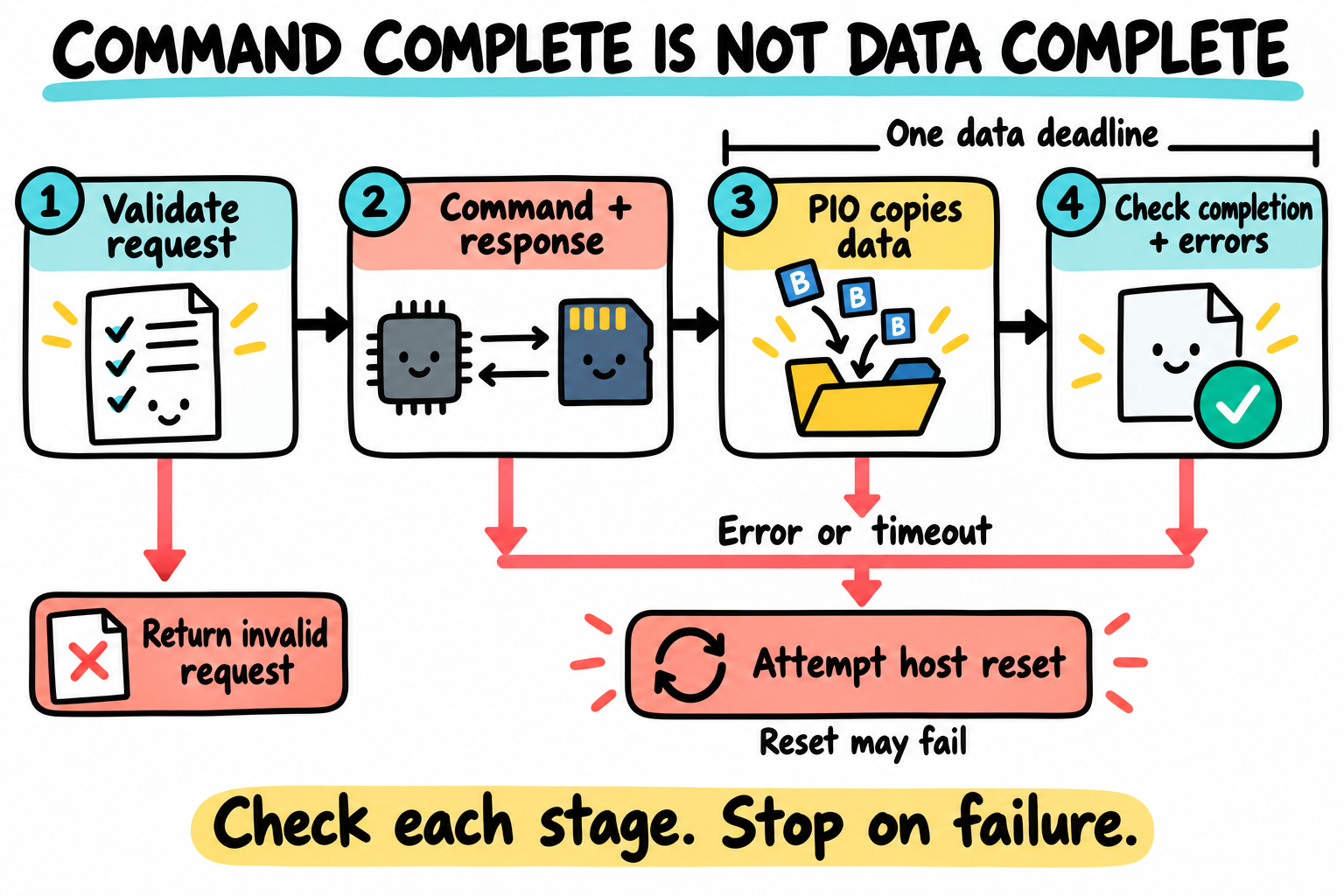
Command completion is not data completion. The driver copies FIFO words, checks completion and returns any error. Host reset is a separate recovery attempt, not proof of card-write integrity. Card and buffer icons are conceptual.
Step |
Function |
What happens |
|---|---|---|
1 |
MMC core |
Creates CMD17 or CMD18 and a destination buffer. |
2 |
|
Validates the request, waits for the command/data path, clears stale status, and sets block attributes. |
3 |
|
Encodes the command and transfer flags; the caller sets |
4 |
USDHC2 hardware |
Sends the command to the eMMC and records completion in |
5 |
|
Copies the controller response registers into |
6 |
|
Waits for |
7 |
Host driver |
Requires transfer complete and checks data timeout, CRC, and end-bit errors. |
8 |
MMC core |
Handles the protocol’s stop/status sequence and exposes the completed block read. |
The protocol decisions remain in U-Boot’s MMC core. The i.MX6ULL register work is entirely in the driver shown above.
Read the driver as a state machine. First validate the request, then wait for the command path to become available. Clear old write-one-to-clear status bits, program block attributes and transfer mode, and write XFERTYP last to launch the command. Command completion is not data completion. For an R1b response without a buffer, DAT0 must release while card clock runs; for a buffered command, every FIFO word and the final TC must complete within one data budget.
The controller’s CICHB flag inhibits the data path; CIDHB inhibits the command path. CMD12 must still be issuable when the data path is active, so it waits only for the command inhibit. This driver does not enable Auto CMD12; the MMC core sends the stop where its protocol requires it. R2 responses are shifted/reassembled because the controller omits the final CRC/end byte. CRC checking remains enabled only for response types that actually contain CRC: CMD1’s R3 response is not one of them.
IRQSTATEN enables status latching even though IRQSIGEN=0 disables the interrupt output. Watermarks are one word, matching the one-word polling loop. A FIFO-ready bit does not override a latched error. Data CRC returns -EILSEQ, timeout returns -ETIMEDOUT, and other transfer framing errors return -EIO. The same deadline covers all FIFO words and final completion; restarting a five-second timeout for each word could otherwise stretch a stalled request enormously. memcpy() avoids imposing alignment on a caller’s buffer while the MMIO FIFO accesses stay 32-bit.
On failure the driver resets command state and, for buffered or busy commands, data state. A reset failure is returned, not discarded. This is host recovery only: it does not prove that a partially written card block is intact. reinit() resets the host for an explicit rescan, and set_ios() respects mmc->clk_disable. No board/card execution was performed to validate these paths. The first configuration disables MMC writes at the core, even though the host listing shows the write FIFO path for study.
24A.17 Add the small legacy configuration header
Create include/configs/imx6ull_point_atom_mini.h:
/* SPDX-License-Identifier: GPL-2.0+ */
#ifndef __IMX6ULL_POINT_ATOM_MINI_CONFIG_H
#define __IMX6ULL_POINT_ATOM_MINI_CONFIG_H

#include <asm/arch/hardware.h>

#define CFG_SYS_SDRAM_BASE             IMX6ULL_DDR_BASE

#define CFG_SYS_INIT_RAM_ADDR          IMX6ULL_OCRAM_BASE
#define CFG_SYS_INIT_RAM_SIZE          IMX6ULL_OCRAM_SIZE

#define CFG_EXTRA_ENV_SETTINGS \
	"kernel_addr_r=0x82000000\0" \
	"fdt_addr_r=0x83000000\0" \
	"console=ttymxc0,115200\0"

#endif
Most feature settings belong in Kconfig, not in this header. Three old-style CFG_* values are still needed here:
Macro |
Use |
|---|---|
|
Lowest usable DDR address |
|
Start of internal RAM used before relocation |
|
Lets generic ARM code place the early stack near the top of OCRAM |
The initial stack address is calculated by common U-Boot as:
OCRAM base + OCRAM size - generated global-data size
We do not choose an unexplained stack constant.
24A.18 Create the complete defconfig
Create configs/imx6ull_point_atom_mini_defconfig:
CONFIG_ARM=y
CONFIG_ARCH_IMX6ULL=y
CONFIG_TARGET_IMX6ULL_POINT_ATOM_MINI=y
CONFIG_TEXT_BASE=0x87800000
CONFIG_SYS_MALLOC_LEN=0x01000000
CONFIG_NR_DRAM_BANKS=1
CONFIG_SYS_MALLOC_F_LEN=0x4000
CONFIG_DEFAULT_DEVICE_TREE="imx6ull-point-atom-mini-from-scratch"
CONFIG_OF_CONTROL=y
CONFIG_OF_SEPARATE=y
# CONFIG_OF_UPSTREAM is not set
# CONFIG_CLK is not set
# CONFIG_PINCTRL is not set
CONFIG_SYS_ICACHE_OFF=y
CONFIG_SYS_DCACHE_OFF=y
CONFIG_BAUDRATE=115200
CONFIG_BOOTDELAY=3
CONFIG_USE_BOOTCOMMAND=y
CONFIG_BOOTCOMMAND="echo U-Boot is ready;"
CONFIG_SYS_PROMPT="imx6ull=> "
CONFIG_SYS_PBSIZE=512
CONFIG_DISPLAY_CPUINFO=y
CONFIG_DISPLAY_BOARDINFO=y
CONFIG_HUSH_PARSER=y
CONFIG_SYS_MAXARGS=32
CONFIG_SYS_LOAD_ADDR=0x82000000
CONFIG_SYS_MEMTEST_START=0x81000000
CONFIG_SYS_MEMTEST_END=0x81800000
CONFIG_CMD_MEMORY=y
CONFIG_CMD_MEMTEST=y
CONFIG_CMD_MMC=y
CONFIG_CMD_FAT=y
CONFIG_CMD_EXT4=y
CONFIG_CMD_FS_GENERIC=y
CONFIG_CMD_DM=y
CONFIG_CMD_SLEEP=y
CONFIG_ENV_IS_NOWHERE=y
CONFIG_ENV_SIZE=0x2000
CONFIG_NO_NET=y
# CONFIG_NET is not set
# CONFIG_EFI_LOADER is not set
# CONFIG_TOOLS_MKEFICAPSULE is not set
CONFIG_DM_SERIAL=y
CONFIG_IMX6ULL_SERIAL=y
CONFIG_TIMER=y
CONFIG_IMX6ULL_GPT_TIMER=y
CONFIG_MMC=y
CONFIG_DM_MMC=y
# CONFIG_MMC_WRITE is not set
CONFIG_IMX6ULL_USDHC=y
What every configuration line does
Configuration |
Why it is enabled or assigned |
|---|---|
|
Builds the ARM architecture instead of another U-Boot architecture. |
|
Adds our machine directory and enables our platform Kconfig. |
|
Selects our board directory and board configuration header. |
|
Links U-Boot to execute at |
|
Reserves 16 MiB in relocated DDR for U-Boot’s dynamic allocations. |
|
Says the board reports one contiguous DDR bank. |
|
Reserves 16 KiB of early allocation space for pre-relocation driver model, taken below the initial stack/global-data area. |
|
Selects |
|
Makes U-Boot discover UART, timer, and MMC from Device Tree. |
|
Appends our local DTB rather than selecting a DT from the upstream Linux DT subtree. |
|
Uses the three explicit clock functions in |
|
Uses the complete pad and daisy writes in the DCD instead of assuming a pin-controller driver exists. |
|
Leaves the instruction cache off during first bring-up. |
|
Leaves the data cache and MMU mapping off during first bring-up. |
|
Sets the normal U-Boot console to 115200 baud. |
|
Waits three seconds before executing |
|
Allows this defconfig to provide a fixed first-stage |
|
Prints one harmless line. It does not attempt to boot Linux yet. |
|
Makes our command prompt easy to recognize. |
|
Allocates a 512-byte console print buffer. |
|
Allows U-Boot to print the CPU information line when available. |
|
Calls |
|
Enables U-Boot’s normal shell parser for variables and command lists. |
|
Allows a command to have up to 32 arguments. |
|
Gives load commands a default destination at |
|
First byte used by our deliberate DDR test. |
|
End of the 8 MiB DDR test window. |
|
Enables |
|
Enables the |
|
Enables |
|
Enables commands for FAT filesystems. |
|
Enables commands for ext4 filesystems. |
|
Enables generic |
|
Explicitly includes the device-tree and timer checkpoint commands used later. |
|
Uses a compiled default environment and never writes persistent storage. |
|
Sizes the environment buffer; it is not a media reservation when the backend is nowhere. |
|
Selects the no-network member of the networking choice and excludes UEFI/capsule tooling. Merely unsetting |
|
Enables the driver-model serial uclass. |
|
Compiles the UART driver we wrote in this chapter. |
|
Enables the driver-model timer uclass. |
|
Compiles our GPT1 timer driver. |
|
Enables the common MMC, SD, and eMMC protocol layer and block-device support. |
|
Enables the driver-model MMC uclass. |
|
Removes block write/erase support from the MMC core for first discovery. It does not forbid all card configuration commands. |
|
Compiles the USDHC2 PIO driver written in this chapter. |
Cache is disabled for first bring-up. Generic ARMv7 entry still establishes the expected CP15 state; later cache enabling is suppressed. Enabling data cache on ARMv7 also entails MMU/page-table and device-memory attributes. Do not copy an ARM64 mem_map[] prescription into this ARMv7 port. Review the ARMv7 cache implementation, valid RAM ranges, MMIO attributes, alignment, and Linux handoff together, then test cache enabling as a separate change.
ENV_IS_NOWHERE is equally deliberate. A wrong environment offset can overwrite an SD partition or eMMC boot area. Persistent environment storage belongs after block access and the storage layout are verified.
24A.19 Check the source tree before building
The final port-owned tree should be:
$ find arch/arm/mach-imx6ull board/point-atom/imx6ull-mini -type f | sort
arch/arm/mach-imx6ull/Kconfig
arch/arm/mach-imx6ull/Makefile
arch/arm/mach-imx6ull/clock.c
arch/arm/mach-imx6ull/cpu.c
arch/arm/mach-imx6ull/early_uart.c
arch/arm/mach-imx6ull/include/mach/clock.h
arch/arm/mach-imx6ull/include/mach/hardware.h
arch/arm/mach-imx6ull/include/mach/uart.h
board/point-atom/imx6ull-mini/Kconfig
board/point-atom/imx6ull-mini/MAINTAINERS
board/point-atom/imx6ull-mini/Makefile
board/point-atom/imx6ull-mini/board.c
board/point-atom/imx6ull-mini/imximage.cfg
Also confirm the remaining created files:
arch/arm/dts/imx6ull-from-scratch.dtsi
arch/arm/dts/imx6ull-point-atom-mini-from-scratch.dts
arch/arm/dts/imx6ull-point-atom-mini-from-scratch-u-boot.dtsi
configs/imx6ull_point_atom_mini_defconfig
drivers/serial/serial_imx6ull.c
drivers/timer/imx6ull_gpt_timer.c
include/configs/imx6ull_point_atom_mini.h
drivers/mmc/imx6ull_usdhc.c
Run U-Boot’s whitespace check before compiling:
$ git diff --check
No output means the tracked diff passed that whitespace check. It does not inspect untracked new files, resolve Kconfig, or validate register values. Review git status --short against the two file inventories; do not accidentally include unrelated experiments. The DDR block is part of the supplied imximage.cfg, so the inventory has no missing board-specific include.
24A.20 Configure and build U-Boot
Build out of tree. A new output directory prevents a previous board’s configuration from leaking into this one and keeps the edited source easy to inspect:
$ . ~/imx6ull/scripts/env.sh
$ UBOOT_BASE=88dc2788777babfd6322fa655df549a019aa1e69
$ test "$(git rev-parse --verify 'v2026.04^{commit}')" = "$UBOOT_BASE"
$ git merge-base --is-ancestor "$UBOOT_BASE" HEAD
$ git log --oneline "$UBOOT_BASE..HEAD"
$ git status --short
$ mkdir -p ~/imx6ull/build
$ UBOOT_OUT=$(mktemp -d ~/imx6ull/build/uboot-24a-v2026.04.XXXXXX)
$ make O="$UBOOT_OUT" CROSS_COMPILE=arm-none-linux-gnueabihf- \
      imx6ull_point_atom_mini_defconfig
$ make O="$UBOOT_OUT" CROSS_COMPILE=arm-none-linux-gnueabihf- \
      -j$(nproc)
Run this block from ~/imx6ull/src/u-boot-24a. The tag check still verifies the upstream identity; the ancestry check accepts either the base itself or your custom descendant commits. Stop if either fails. Review the displayed commits and local changes: ancestry alone does not prove that only the intended chapter edits are present. Do not use git describe --exact-match HEAD as a post-feature-commit requirement, or reset away Chapter 21’s custom command just to obtain that output.
The configure command resolves the defconfig through Kconfig into $UBOOT_OUT/.config. The build compiles target code with the ARM compiler and host tools with native GCC. Keep UBOOT_OUT in this shell for the remaining commands. No image-header target is wired into our custom machine Makefile: this build produces u-boot.bin, not the standard EVK’s u-boot-dtb.imx.
Confirm the important generated values:
$ grep -E 'CONFIG_(ARCH_IMX6ULL|TEXT_BASE|DEFAULT_DEVICE_TREE|IMX6ULL_SERIAL|IMX6ULL_GPT_TIMER|IMX6ULL_USDHC)=' "$UBOOT_OUT/.config"
Required configuration values, not a captured board log:
CONFIG_ARCH_IMX6ULL=y
CONFIG_TEXT_BASE=0x87800000
CONFIG_DEFAULT_DEVICE_TREE="imx6ull-point-atom-mini-from-scratch"
CONFIG_IMX6ULL_SERIAL=y
CONFIG_IMX6ULL_GPT_TIMER=y
CONFIG_IMX6ULL_USDHC=y
Confirm that the main artifacts exist:
$ ls -l "$UBOOT_OUT"/u-boot "$UBOOT_OUT"/u-boot.bin \
        "$UBOOT_OUT"/u-boot.map "$UBOOT_OUT"/dts/dt.dtb \
        "$UBOOT_OUT"/tools/mkimage
$ arm-none-linux-gnueabihf-readelf -h "$UBOOT_OUT/u-boot"
$ arm-none-linux-gnueabihf-nm -n "$UBOOT_OUT/u-boot" | head
u-boot is the ELF file with symbols. u-boot.bin is the flat executable with the selected DTB appended. u-boot.map shows where every function and section was linked. dts/dt.dtb is the compiled board Device Tree.
Check that the ELF is ARM and _start is at 0x87800000. In .config, also check SKIP_LOWLEVEL_INIT_ONLY=y, SYS_ICACHE_OFF=y, SYS_DCACHE_OFF=y, the three custom drivers, and the disabled MMC-write/high-speed features. Decompile the built DTB with $UBOOT_OUT/scripts/dtc/dtc -I dtb -O dts "$UBOOT_OUT/dts/dt.dtb" and inspect its selected console, timer, one-bit MMC width, and 20 MHz ceiling. A disabled Kconfig option can disappear during dependency resolution; reading the generated file is more reliable than assuming the defconfig line took effect.
The complete listings, including the documented vendor DDR block, were compiled in a fresh private copy of the pinned upstream source with Arm GNU 13.2.Rel1 during this review. The actual image was then generated and its encoded DCD compared with the vendor source. These establish source and image milestones only. This custom port was not executed on a board.
Read build failures literally
Error |
Most likely missing step |
|---|---|
|
The |
|
The MMC Makefile line exists, but the driver filename is wrong or missing. |
|
The machine line in |
|
|
|
The USDHC driver is enabled, but |
|
The DTS Makefile line or |
Missing |
Host build dependency or its private include/tool path, not an ARM peripheral bug. |
Do not respond to the first compiler error by enabling unrelated Kconfig symbols. Follow the filename and symbol named by the error.
24A.21 Build the i.MX Boot ROM image
u-boot.bin alone is not bootable on this SoC. It has no i.MX IVT, Boot Data, or DCD. Build those around it in two visible commands.
Section 24A.14 now supplies every directive, including the documented DDR block. Preprocess the configuration to remove C comments. This uses the actual board image configuration, not a substitute header-format fixture:
$ cpp -P -x c board/point-atom/imx6ull-mini/imximage.cfg \
      -o "$UBOOT_OUT/u-boot.cfgout"
Then run the U-Boot host tool:
$ "$UBOOT_OUT/tools/mkimage" \
      -n "$UBOOT_OUT/u-boot.cfgout" \
      -T imximage \
      -e 0x87800000 \
      -d "$UBOOT_OUT/u-boot.bin" \
      "$UBOOT_OUT/u-boot-imx6ull.imx"
Every argument has a specific job:
Argument |
Meaning |
|---|---|
|
Read our image version, SD boot type, and DCD writes. |
|
Generate the i.MX Boot ROM image format. |
|
Put |
|
Use our complete U-Boot binary as the payload. |
|
Name of the resulting SD-card image. |
Inspect the generated header:
$ "$UBOOT_OUT/tools/dumpimage" -l "$UBOOT_OUT/u-boot-imx6ull.imx"
The report should identify an i.MX image and show the 0x87800000 entry address. Also check that the image is larger than u-boot.bin because it contains the ROM header and DCD:
$ ls -l "$UBOOT_OUT/u-boot.bin" "$UBOOT_OUT/u-boot-imx6ull.imx"
Read the actual IVT and Boot Data fields as well. This small host-side check decodes little-endian words and resolves the Boot Data pointer relative to self:
$ python3 - "$UBOOT_OUT/u-boot-imx6ull.imx" "$UBOOT_OUT/u-boot.bin" <<'PY'
import struct
import sys
from pathlib import Path

image = Path(sys.argv[1]).read_bytes()
payload = Path(sys.argv[2]).read_bytes()
assert image[:4] == bytes.fromhex("d1 00 20 40"), "Not this v2 IVT"
entry, reserved, dcd, boot_data, self, csf, reserved2 = struct.unpack_from("<7I", image, 4)
start, size, plugin = struct.unpack_from("<3I", image, boot_data - self)
assert (entry, self, boot_data, dcd, start, plugin, csf) == (
    0x87800000, 0x877FF400, 0x877FF420, 0x877FF42C, 0x877FF000, 0, 0)
assert image[0xC00:0xC00 + len(payload)] == payload, "Payload differs"
assert size >= 0x1000 + len(payload), "Boot Data load size is too small"
for name, value in (("entry", entry), ("self", self), ("DCD", dcd),
                    ("Boot Data pointer", boot_data), ("Boot Data start", start),
                    ("Boot Data size", size)):
    print(f"{name}: 0x{value:08X}")
PY
These assertions are specific to this chapter’s non-plugin, unsigned SD image. They detect a changed layout or payload, not DDR electrical faults. The encoded DCD must also retain section 24A.14’s ordered vendor block and teaching pad/reset additions.
What mkimage adds
u-boot-imx6ull.imx
|-- IVT header
|-- entry = 0x87800000
|-- DCD pointer
|-- Boot Data pointer
|-- self pointer
|-- DCD command table from u-boot.cfgout
|-- padding and payload metadata
`-- u-boot.bin
The IVT field named self contains the RAM address where the ROM sees that IVT. It does not mean that the IVT executes code. The ROM reads the structure and follows its pointers.
Do not confuse three address spaces: an offset inside the .imx file, a byte offset on the card, and a RAM address from the IVT. For this v2 SD format, include/imximage.h sets an initial load region of 0x1000 and an IVT media offset of 0x400. The generated file starts at the IVT, so its payload starts at file offset 0xC00; placing the file at card byte 0x400 puts the payload at card byte 0x1000.
Item |
File offset / value for this layout |
|---|---|
IVT |
File |
Boot Data |
File |
DCD |
File |
Payload |
File |
Boot Data start |
|
These relationships follow the pinned tools/imximage.c generator. Check them again if the format, boot medium, plugin mode, or header sizing changes. In this release, dumpimage’s v2 line labelled Load Address prints the Boot Data pointer, so it is not sufficient evidence for the payload load address. Boot Data size includes the image load layout and alignment; do not substitute the raw binary length. Image inspection proves pointer/layout consistency, not that the DCD will initialize the physical DDR.
24A.22 Write the image to an SD card
This is a later hardware procedure, not part of the source-build example. Confirm the fitted core matches the documented DDR target and complete the image/layout checks before using a dedicated expendable card. Establish a power-off/recovery plan for this untested teaching runtime, and retain Chapter 19’s vendor baseline. A write beginning at 1 KiB can still overwrite a GPT entry array or an existing bootloader. Use a reviewed raw/MBR layout with an explicitly reserved boot gap; this offset is not a general guarantee of partition safety.
Identify the whole removable device by size, model, transport, and physical insertion/removal before doing anything destructive:
$ lsblk -o NAME,SIZE,MODEL,TRAN,MOUNTPOINTS
In the commands below, /dev/sdX means the whole card. Replace sdX with the real device. Do not use a partition such as /dev/sdX1.
Record the resolved whole-device path and verify it is the intended card, not a system disk. Back up anything needed. Unmount each mounted partition by its exact name and stop on any error; do not hide failures behind a wildcard and || true. Confirm the image fits wholly within the reserved boot gap before proceeding. The following SD_DEVICE is a placeholder that must be assigned to that verified whole device, never a partition:
$ SD_DEVICE=/dev/sdX
$ sudo dd if="$UBOOT_OUT/u-boot-imx6ull.imx" of="$SD_DEVICE" \
          bs=1K seek=1 conv=fsync,notrunc status=progress
$ sync
bs=1K seek=1 skips 1 KiB, which is offset 0x400. This matches this image’s SD IVT position. Writing the same file at zero puts the IVT in the wrong place. Do not add another 1 KiB of padding to a file that already begins with the IVT.
Read back and compare the whole image, not just its first 64 bytes:
$ IMAGE_SIZE=$(stat -c %s "$UBOOT_OUT/u-boot-imx6ull.imx")
$ sudo dd if="$SD_DEVICE" of="$UBOOT_OUT/sd-readback.imx" \
      iflag=skip_bytes,count_bytes skip=1024 count="$IMAGE_SIZE" status=none
$ cmp "$UBOOT_OUT/u-boot-imx6ull.imx" "$UBOOT_OUT/sd-readback.imx"
cmp must exit successfully with no differences. This confirms stored bytes, not ROM acceptance or board operation. No card writes or readbacks were performed during this review.
24A.23 Connect the built-in console and boot
The board already contains the USB-to-TTL bridge. Do not connect an external USB-to-TTL adapter.
Connect the board’s USB debug or serial connector to the host.
Find the new device with
dmesgorls /dev/ttyUSB* /dev/ttyACM*.Open it at 115200 baud.
Set the board boot switches to SD mode.
Insert the prepared SD card.
Power-cycle the board.
For example:
$ picocom -b 115200 /dev/ttyUSB0
Use the actual device name. The terminal settings are 115200 baud, 8 data bits, no parity, and 1 stop bit. Hardware flow control must be off.
Capture the complete terminal log from power-on. This chapter does not supply a fabricated successful boot transcript. Look for the literal strings our code emits: [imx6ull] arch_cpu_init reached, then [imx6ull] board_early_init_f reached. Later, a banner and imx6ull=> establish further checkpoints. The 512 MiB report is the configured bank assignment, not a DDR measurement. Preserve missing, partial, or garbled output as evidence rather than adjusting the log to match an example.
24A.24 Test one subsystem at a time
Test the timer
imx6ull=> sleep 1
imx6ull=>
The prompt should return after about one second. An immediate return or a permanent hang points to GPT clock, reset, prescaler, or Device Tree selection.
Inspect the memory map
imx6ull=> bdinfo
Check these values in the output:
DRAM bank   = 0x00000000
-> start    = 0x80000000
-> size     = 0x20000000
The relocation address should be inside DDR and must not overlap the test window at 0x81000000 to 0x817FFFFF.
Test DDR without overwriting U-Boot
imx6ull=> mtest 0x81000000 0x81800000 0x00000000 1
This is a half-open 8 MiB window with the default quick-test implementation. Check the compiled test variant before interpreting an endpoint: alternative tests and optional bit-flip checks have different accesses. Even this aligned range is destructive and is not automatically free just because it lies below U-Boot’s relocation address. Verify the full runtime reservations and any loaded buffers first, then stop on any mismatch. Do not extend a running U-Boot memory test over its own stack, heap, DTB, or executable. A small successful scratch test does not qualify the whole DDR bank or its calibration.
Test eMMC discovery
imx6ull=> mmc list
imx6ull=> mmc dev 0
imx6ull=> mmc info
imx6ull=> mmc part
What to record if discovery succeeds:
mmc listshowsi.MX6ULL USDHC2 PIO.mmc dev 0selects it without a timeout.mmc infoidentifies MMC/eMMC rather than an SD card and shows the negotiated legacy mode, one-bit bus, and actual divided clock.mmc partprints the existing partition table, if one is present.
Do not run mmc write during first discovery. Reading identification and partition data proves the controller path without changing storage.
Compare CID manufacturer/product/revision and capacity against the fitted part’s record. CSD/EXT_CSD capacity and mode bits distinguish what the card supports from what the host currently advertises. non-removable means no mechanical card detect; it does not prove that a chip is connected. A missing partition table is not an identification failure. A valid partition listing examples only a few sectors, not the whole medium. Initialization still sends volatile card configuration commands even with block writes disabled; do not use partition, boot configuration, RPMB, erase, or reset-function commands here.
24A.25 Diagnose silence by the last completed stage
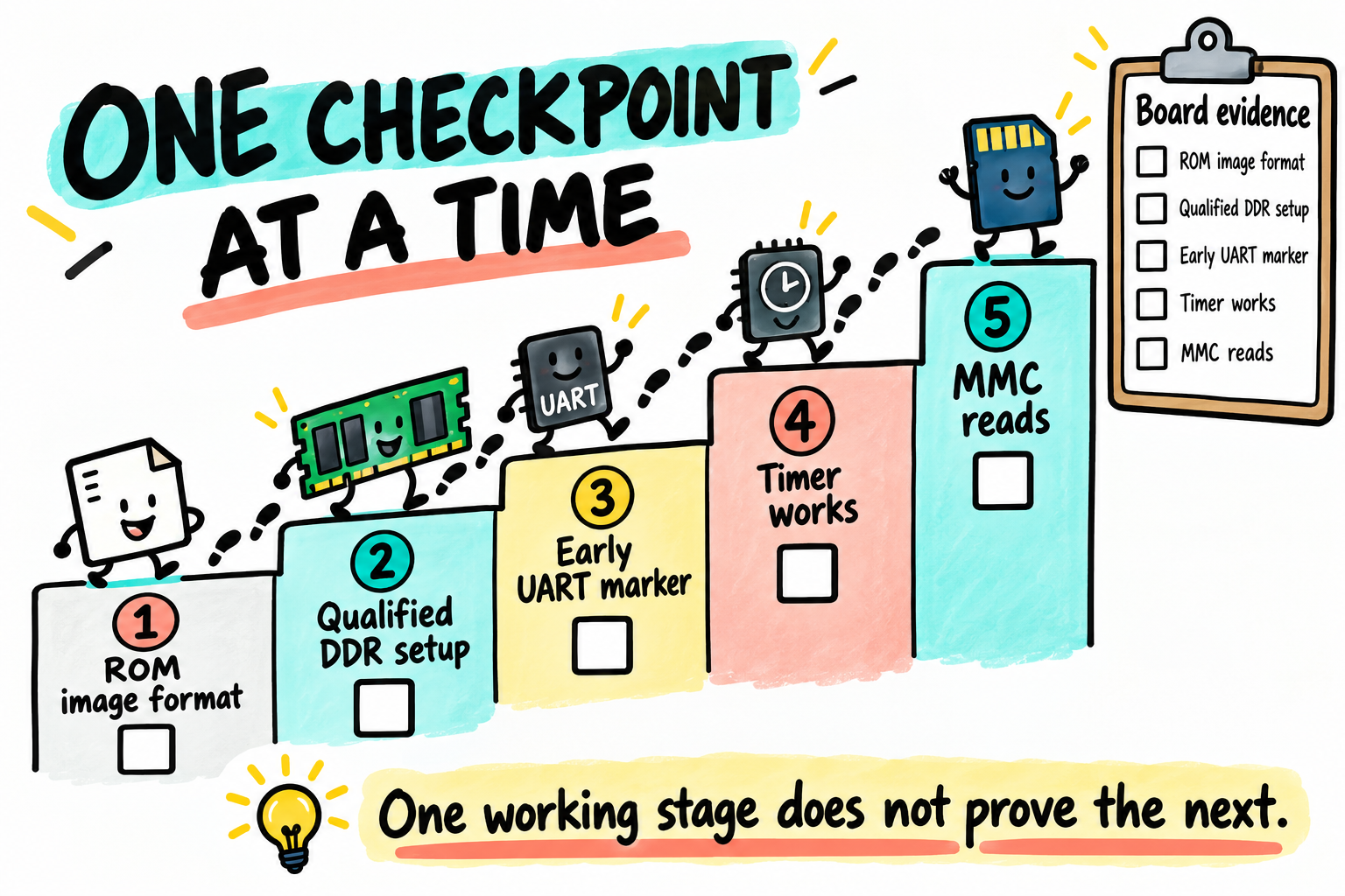
Gather evidence one stage at a time. An early marker narrows the search, but does not qualify DDR or prove a later peripheral works. The memory and card drawings are conceptual symbols, not a board layout.
Last visible result |
What has already worked |
Check next |
|---|---|---|
No serial device appears on host |
Nothing about the SoC yet |
USB cable, board power, and built-in USB-to-TTL bridge |
Serial device appears, but no text |
Host connection only |
SD boot switch, image at offset |
Garbled text |
UART transmits |
Baud rate, 24 MHz UART selection, terminal flow control |
|
ROM, DDR load, ARM startup, clocks, and early UART |
|
Both markers, no U-Boot banner |
Board early hook works |
timer probe, Device Tree inclusion, relocation, BSS or DDR corruption |
Banner, but wrong DRAM size |
Pre-relocation console works; relocation is not yet proven |
|
Prompt works, |
Most of U-Boot works |
GPT node, GPT clock gate, |
Prompt works, |
DDR, timer, and console work |
eMMC pad mux, daisy values, USDHC2 clock, reset line, voltage |
This table is why the early markers are direct register writes. They remain available even if driver-model serial or relocation fails.
Inspect the final Device Tree from U-Boot
At the prompt:
imx6ull=> dm tree
Look for the serial, timer, and MMC uclasses, with nodes at the expected addresses and their probe indicators. dm tree commonly displays node/device names, such as serial@2020000, not necessarily the U_BOOT_DRIVER identifier. dm drivers can help inspect registered driver names. Binding means a compatible driver was found; probing means its initialization callback succeeded; neither proves successful eMMC identification.
If a device is absent, first check its Kconfig symbol and Device Tree compatible. If it is present but not probed, inspect its reg, status, and required clock setup.
24A.26 What is complete and what is deliberately absent
The supplied source covers the teaching runtime and can be built against the pinned release. It is not a claimed board-qualified image. The source includes:
A new ARM machine selection
A new board target
Direct early clock and UART code
A driver-model serial driver
A driver-model timer driver
A driver-model USDHC2 PIO driver
A complete ROM image configuration with the pinned vendor’s documented 512 MiB eMMC-core DDR initializer
A SoC
.dtsiand board.dtsA complete defconfig
Reproducible image creation, later SD provisioning, and separate physical verification procedures
These features are not silently assumed. They are deliberately postponed:
Feature not added |
Reason to add it later |
|---|---|
SPL |
A different boot-chain design, not a missing stage of this MINI ROM+DCD flow. Any Chapter 20 SPL example is a separate source/build-only reference, not a MINI image. |
Data cache and MMU |
Need a tested memory-region map. Enable them after the basic port is stable. |
Pin controller driver |
The first DCD performs the exact pad writes. A reusable pinctrl driver becomes useful when many peripherals and runtime pin states are added. |
Clock controller driver |
The first port has three explicit clock consumers. A driver-model clock tree becomes useful as the peripheral count grows. |
Wider/faster MMC, DMA, and tuning |
First prove legacy one-bit reads. Wider buses need line checks; high speed needs qualified pad/timing settings. DMA and advanced modes add cache, descriptor, voltage, and sampling work. |
Persistent environment |
Needs a reviewed eMMC or SD offset and erase/write policy. |
Ethernet, USB, NAND, display |
They do not help prove the minimum boot chain. Add one driver and one visible test at a time. |
Linux boot command |
Chapter 23 builds |
Postponed does not mean optional forever. It means the feature is outside the first dependency chain and has a named later step.
Qualification also remains outside the source result: we did not measure DDR calibration, full-bank stability, inherited clocks/watchdogs, boot straps, eMMC rails/reset, or controller/card error recovery. The DDR values have vendor-source provenance, while our peripheral drivers and additional pad/reset policy remain untested on hardware. Product hardening would additionally review security state, silicon revision/errata, reset/power management, watchdog servicing, and kernel handoff. Do not turn an unchecked item into a successful result by changing a chapter label from draft to complete.
24A.27 The porting method to carry to a truly new SoC
The names and register values will change on another chip, but the method remains:
Write the exact Boot ROM load contract and memory map.
Prove DDR with visible low-level code or a visible ROM configuration table.
Add the architecture Kconfig and machine Makefile connection.
Provide the early stack addresses and DDR bank description.
Print one direct UART marker before relying on the console framework.
Add a monotonic timer before enabling timeout-dependent drivers.
Describe devices in Device Tree and match each
compatibleto one driver.Implement the smallest polling driver that proves each new peripheral before adding DMA, interrupts, or tuning.
Explain every defconfig option by the code or behavior it enables.
Build the exact ROM image format and verify it after writing the boot medium.
Test one subsystem at the prompt before adding the next one.
The core skill is not copying a vendor directory. It is making every dependency visible, then proving those dependencies in an order that leaves useful evidence when the board stops.
24A.28 Key Notes
The port joins several contracts: ROM image layout, early ARM runtime, U-Boot relocation, Device Tree discovery and peripheral framework callbacks. A correct interface at one stage does not establish the next.
An early UART can use bounded private polling before the driver model exists. The later serial callback must follow its framework’s readiness semantics rather than block indefinitely.
MMC response type, transfer deadlines and recovery ordering belong to the controller/protocol boundary. Extending a deadline after every word is not the same policy as bounding the whole transfer.
The vendor DCD supplies named DDR initialization values for a documented core-board design. Source provenance and successful compilation are not measured calibration or physical memory qualification.
File placement, media placement and loaded RAM pointers must agree in the ROM image. Header readback and a printed memory size cannot prove full storage integrity or DDR stability.
This teaching route intentionally omits platform responsibilities. A product port still needs power, reset, security, errata and failure recovery ownership beyond the three small drivers.
Primary sources for this chapter
Official Alientek eMMC-core DCD and its defconfig establish the copied initializer. The supplied guide V1.81 page 7, DDR pages 525-550, and chapter 33 pages 860-911 establish MINI applicability and the documented eMMC-core design. The supplied core V2.0 schematic confirms the labelled DDR and wiring, not our own bench validation.
Pinned U-Boot source:
arch/arm/cpu/armv7/start.S,arch/arm/lib/crt0.S,common/board_f.c, andcommon/board_r.cestablish startup and relocation.Image generator and format definitions establish the IVT/DCD layout. EVK documentation describes that board’s DCD image, not a MINI qualification.
MMC API, MMC core, and upstream USDHC implementation are comparison evidence for callback/protocol contracts, not hidden linked drivers in this custom port.
NXP i.MX6ULL documentation, especially IMX6ULLRM Rev. 1 chapters 8 (ROM), 18 (CCM), 30 (GPT), 32 (IOMUXC), 35 (MMDC), 55 (UART), 58 (USDHC), and 59 (WDOG). The supplied core/baseboard schematics establish candidate wiring; fitted-part and calibration evidence must still come from the board record.