Chapter 2: What “Embedded Linux” actually is
You already know how to turn on an LED. Choose the pad, enable the clock, set the direction, and write the GPIO register. If your board runs MCU firmware, your application can usually follow that path itself.
Now imagine putting the same register-writing function in a Linux application. The C may compile. The physical address may be correct. Neither fact gives the application permission or a mapping to use that register.
The LED has not become more complicated. The board has become a shared machine. A shell, a network service, and your application can run independently, and one bad pointer should not casually overwrite the others’ memory. Linux changes the rules around the operation so those programs can coexist. Let us follow what that means, starting with the firmware model you know.
2.1 The system you already understand
Think back to the startup code in a Cortex-M project. At reset, the CPU obtains its initial stack pointer and reset-handler address from the device’s vector arrangement. The vector table contains those values; it is not itself a sequence of instructions. The reset handler prepares RAM, copies .data, clears .bss, and calls main(). Your program then enters its main loop or starts an RTOS scheduler.
In a typical project, the application, its drivers, and the RTOS are linked into one image. Tasks may have different stacks and priorities, but they commonly share one physical address space. Pass a buffer pointer to an I2C driver, and both pieces of code use the same address to reach the same bytes. Both can use the pointer directly.
Most such projects also let application code access peripheral registers directly. Cortex-M does support privileged and unprivileged execution, and an MPU can add protection on parts that have one, but many projects do not use that separation. A call such as i2c_read(addr, buf, len) goes straight into the driver’s code.
Add FatFS or littlefs, a network stack, and several RTOS tasks, and the project may already look quite capable. Linux does not make those ideas new. What happens if we want programs built independently, with private memory and controlled access to the devices they share? That is where the familiar direct-call model starts to change.
2.2 The four layers
An embedded Linux system can be viewed as four software layers above the hardware. During boot, control moves from the Boot ROM to the bootloader, then to the kernel, which starts user-space programs.
Keep three things separate: the source we edit, the files produced by a build, and the running software with its registers, memory, and state. An executable file in /bin is not yet a process. The root filesystem is the target’s directory tree mounted at /; it supplies programs, configuration, and any required libraries. The target does not need the kernel’s C source tree installed to run Linux.
The picture names the main roles and some typical input files, not a compulsory one-file boot recipe. A bootloader can have stages such as SPL and U-Boot. On this SoC, the ROM can also apply image-supplied hardware settings before entering the loaded code; Chapter 7 explains that route.
   ┌──────────────────────────────────────────────────────────────┐
   │  Layer 4: User space                                         │
   │  shell, applications, daemons, your code                     │
   │  (files in /bin, /sbin, /usr/bin, ...)                       │
   ├──────────────────────────────────────────────────────────────┤
   │  Layer 3: Linux kernel                                       │
   │  scheduler, memory management, filesystems, drivers, network  │
   │  (vmlinux, zImage)                                           │
   ├──────────────────────────────────────────────────────────────┤
   │  Layer 2: Bootloader  (U-Boot)                               │
   │  initialize DRAM, load kernel from SD/eMMC/network,          │
   │  pass control + device tree + cmdline                        │
   │  (u-boot.imx)                                                │
   ├──────────────────────────────────────────────────────────────┤
   │  Layer 1: Boot ROM  (on-chip mask ROM)                       │
   │  select device, find image header, load bootloader           │
   │  (immutable, lives inside the SoC)                           │
   ├──────────────────────────────────────────────────────────────┤
   │  Layer 0: Hardware  (i.MX6ULL + DDR + peripherals)           │
   └──────────────────────────────────────────────────────────────┘
Read the diagram from the bottom upward, as a sequence of handoffs. At reset, there is no shell waiting to launch your application. The lower stages must make that possible first.
The Boot ROM runs first. NXP puts this small firmware inside the chip during manufacture. We cannot replace it, so our first image must use the header and placement it expects. Chapter 7 explains that format and how the ROM finds our code.
The bootloader prepares and loads the system. We use U-Boot. Its early code configures clocks and DDR, and its drivers can fetch files from storage or the network. Much of this will look familiar from MCU work. Its destination, however, is another program: the Linux kernel. In Part II, our own small bare-metal programs temporarily occupy this place in the boot sequence.
The kernel manages the running system. Once U-Boot hands over control, Linux schedules work, manages memory, and controls access to devices. Drivers are part of this layer. They turn requests such as “send these bytes” into the register operations needed by a particular UART or network controller.
User space is where applications run. It includes your program, the shell, and background services, often called daemons. These programs use interfaces provided by the kernel rather than assuming that every peripheral register is available to them.
By the time your application starts, the ROM and bootloader have already done their work. Your ordinary device requests go to the running kernel, not back down through every boot stage. For our LED, the important boundary is now the last one in the diagram: the application is in user space, and the driver is in the kernel. How does a request cross that boundary?
2.3 The user/kernel split, made concrete
On our Linux system, application instructions and kernel instructions run with different CPU privileges. The Cortex-A7 calls ordinary application execution USR mode. Kernel exception handlers use privileged modes such as SVC and IRQ; Chapter 4 explains those names in detail.
Kernel execution can use privileged system-control operations and kernel memory mappings.
User execution cannot use privileged instructions or access protected kernel memory. An application also has no automatic mapping of peripheral registers; the kernel decides which interfaces or mappings it may use.
The CPU enforces this distinction. A user instruction that tries to write to protected kernel memory causes an exception, rather than completing the write. The kernel handles that exception and normally terminates the offending process. We will meet processes shortly; for now, think of one as a running application with its own resources.
There is an easy trap here. If sudo gives a program root privileges, has it crossed into kernel mode? No. Root is a Linux user identity; kernel mode is a CPU execution state. Later, sudo picocom gives the serial terminal credentials to open a restricted device, but its own instructions still run in user mode. The kernel checks those credentials when the program requests access. The need for sudo comes from device permissions, not from a rule that hardware always needs root.
An application requests a kernel service through a system call, usually shortened to syscall. On ARMv7-A, the svc instruction raises a Supervisor Call exception. The CPU enters the kernel handler in SVC mode, where Linux reads the syscall number from r7 and its arguments from r0 onward. After handling the request, the kernel returns a result to the application.
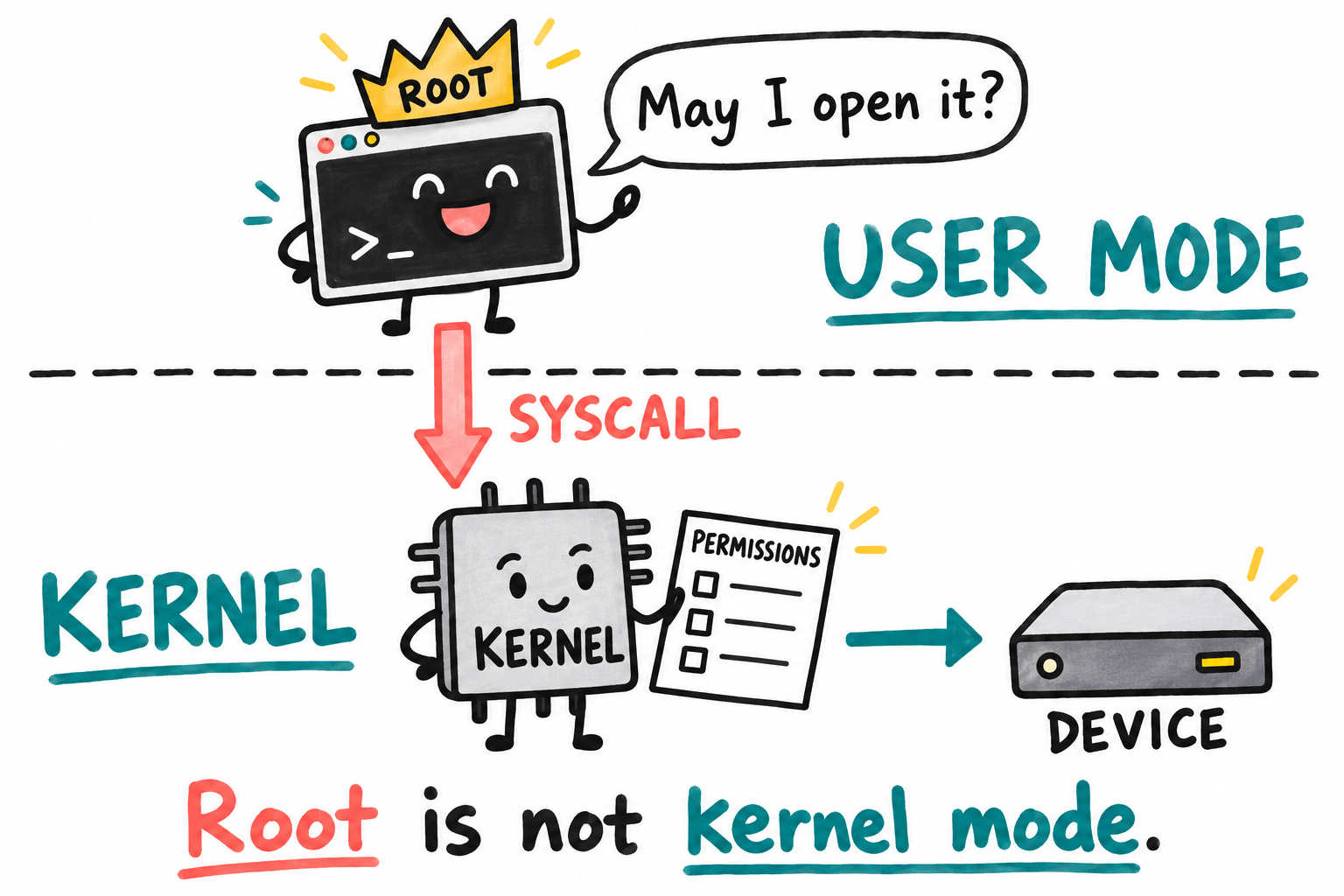
Nice crown. Still user mode. Root credentials can change the kernel’s permission decision, but they do not turn the application’s instructions into kernel instructions. The arrow follows a device request, not every instruction the application executes.
Here is a simplified path for opening an example I2C bus interface. /dev/i2c-0 is a device-interface pathname. An fd, or file descriptor, is the small integer handle returned on success; Section 2.6 follows its lifetime. libc is the application’s C library; glibc is one implementation. The application calls its ordinary C function, and the library wrapper performs the transition into the kernel:
    user-space process            kernel
    ───────────────────────       ──────────────────────────
    fd = open("/dev/i2c-0",..)
        ↓ glibc wrapper builds
        ↓ syscall args
        svc #0        ────────►   exception handler
                                  → sys_openat()
                                  → kernel parses path
                                  → finds i2c_dev driver
                                  → driver's .open() runs
                                  → returns fd
                       ◄────────  return from exception
    fd in r0, back in user mode
Opening /dev/i2c-0 only obtains a bus handle; it does not select an I2C peripheral or transfer bytes yet. The adapter number is illustrative, not a promise about this board. Later requests supply the address and operation.
Most application requests to the kernel take this shape. Reading a file uses read(). Allocating memory may use brk() or mmap(). Sleeping may use nanosleep(). To control an LED, an application may call write() on a device interface or use ioctl() on a device node. These operations cross the user/kernel boundary through syscalls and return a result or error to the application, which resumes in user mode. Non-root programs make syscalls too.
Not every C function needs a syscall every time it runs. malloc() can reuse memory the library already obtained, for example. If a driver authorizes a memory mapping, later loads and stores through that mapping do not each require a syscall. The kernel sets up and controls the access; it does not have to execute every instruction on the application’s behalf.
Linux documents its syscall interfaces in section 2 of the manual. On a Linux host, man 2 read opens the description of read(). You do not need to learn the syscall list now. First understand the request, the transition into the kernel, and the return to the caller.
Why the split exists
Suppose a network service has a bad pointer. You would rather lose that service than let it overwrite the application’s state or the kernel’s scheduler. Suppose two programs want the I2C bus. Their requests need coordination, even though neither program knows the other’s code. Linux’s separation addresses these problems:
Robustness. A bad pointer in an ordinary application is normally contained by its mappings and permissions, rather than overwriting kernel data or another program’s private memory.
Access policy. A driver can check which operations a caller is allowed to request, rather than giving every program unrestricted control of its hardware.
Resource arbitration. Many processes want the I²C bus, the CPU, or the network. The kernel coordinates supported transfers and schedules work. It does not automatically turn several separate application requests into one atomic device protocol; drivers and applications still need appropriate ownership or locking.
For one tightly controlled firmware image, a smaller RTOS and direct driver calls may be the right design. Linux takes on a different job: managing independent programs and the resources between them. Its driver boundary starts to make sense once more than your one application needs the board.
2.4 Virtual memory, in one section
Start with bare-metal code using physical addresses, with the MMU disabled. This is symbolic pseudocode, not a register write to run:
*(volatile uint32_t *)PHYSICAL_REGISTER_ADDRESS = value;
The manual supplies a block base and each register’s offset; together they give the physical register address. For example, 0x020E0000 is the i.MX6ULL IOMUXC block base, not a pad register to write at offset zero. A valid register access must also follow that register’s width and access rules.
Carry that same number into a Linux application and a less obvious question appears: is it still the address of that register?
With the MMU enabled, a user-space pointer is usually a virtual address, not a direct physical bus address. Before the CPU can load or store memory, the MMU translates:
virtual address used by the program
        |
        v
MMU looks in the current process page table
        |
        v
physical address in RAM or in a device register block
Consider two applications that both have a pointer with the value 0x00010000. In the shared MCU model, the same address would normally reach the same bytes. With separate process mappings, it need not. The following illustrative addresses show the difference; they are not a required Linux memory layout:
Process A:
  virtual 0x00010000  -> physical RAM for process A's code
  virtual 0x000B0000  -> physical RAM for process A's data
  virtual 0xBE000000  -> physical RAM for process A's stack

Process B:
  virtual 0x00010000  -> physical RAM for process B's code
  virtual 0x000A0000  -> physical RAM for process B's data
  virtual 0xBE000000  -> physical RAM for process B's stack
Look at 0x00010000 in both lists. The numbers match, but the physical RAM can be different. The current process’s mapping gives the pointer its meaning. Each application can therefore work with its own code, globals, and stack without first finding a free physical address above every other application’s allocations.
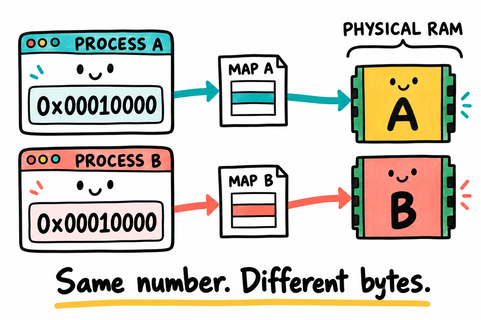
Matching numbers need not mean matching bytes. Here, each process has a private mapping to a different RAM region. Those regions can belong to the same chip. Shared mappings can instead lead to the same physical pages.
The page table describes this translation and its access permissions. A page is a fixed-size unit of memory; the ordinary small-page mappings in this route use 4 KiB pages. You can think of the table as a map owned by the kernel:
For process A:
  virtual page X -> physical page Y, readable and executable
  virtual page Z -> physical page W, readable and writable
  some pages     -> not mapped at all
What if a translation is missing, or its permissions do not allow the attempted access? The CPU raises a memory-access exception that Linux handles as a page fault. The name sounds like a program has already gone wrong, but that is not always the case. Linux must decide whether the access is valid and can be completed.
The kernel may decide:
This address is valid but not loaded yet, so allocate RAM and continue.
This address belongs to a file mapping, so attach an already cached page or fetch the file data if needed, then continue.
This is a permitted write to a private copy-on-write page, so supply a private copy and retry the instruction.
This access is invalid or prohibited, so deliver
SIGSEGV, whose default action terminates the process.
This also separates an address range from the RAM currently backing it. A process can have a valid range for which physical pages are supplied as needed. The kernel decides whether a fault can be resolved or whether the access must be rejected.
Several later Linux features build on this mechanism. Treat the names below as examples of where the idea leads, not as APIs to memorize before Chapter 3:
Process isolation. An ordinary store can reach only memory mapped for that process with the required permissions. Private mappings protect another process’s private state. Deliberate shared mappings and authorized cross-process operations are different cases; process separation is not an unconditional sandbox.
Memory-mapped files. For a regular file,
mmap()can give the program a virtual range instead of a separateread()buffer. Missing translations may fault; resident, permitted pages need no syscall or storage read for each access. The same API can also create anonymous memory or a driver-authorized device mapping.fork(). A child initially shares many physical pages with its parent. Private writable pages can be mapped read-only so that a write faults; Linux makes a private copy when required and resumes the instruction. This is copy-on-write. Sharing a physical page does not mean either process may silently change the other’s private view.
Shared libraries. A library such as
libc.socontains common code used by many programs. Linux can map the same physical code pages into many processes, while each process still has its own private stack and heap.Swap. Swap means the kernel can move idle memory pages out of RAM and onto storage, then bring them back later. Embedded systems often disable swap, but it uses the same page-table and page-fault machinery.
Now return to the i.MX6ULL IOMUXC register block at physical address 0x020E0000. A normal user process does not automatically have that physical address in its page table. If the process tries to treat 0x020E0000 as a pointer, the MMU interprets it as a virtual address. Unless the kernel deliberately mapped that virtual page for the process, the access faults.
We can now explain the opening puzzle. The physical GPIO address from the manual is not automatically a usable pointer in the application. The normal route is to request an operation through a driver interface. The driver reaches the hardware using the appropriate mappings and register accesses. The address was correct; our assumption about who could use it was not.
Chapter 17 follows a minimal first-level page table on bare metal, making the translation and permission decisions visible without Linux’s larger memory-management machinery.
2.5 Processes, threads, and where they live
An RTOS task gives you a familiar starting point: execution needs registers, a stack, and scheduler state. In Linux, that execution is a thread. A process groups one or more threads together with the resources they share.
A process has:
A unique PID (process ID).
A virtual address space (its own page table).
A set of open file descriptors (more on these in a moment).
A current working directory, a user ID and group ID (UID/GID), signal handlers, resource limits, and other state visible under
/proc/<pid>/.
Threads within the process share its address space and file descriptors, but each has its own registers, stack, and execution state. Linux represents a schedulable thread as a task with a struct task_struct. The distinction is useful: two threads in one application can share a global variable directly, while two independent processes need an agreed sharing mechanism.
What about ISRs? A Linux hard interrupt handler runs in kernel interrupt context and must not sleep or make blocking allocations. Its stack arrangement depends on architecture and configuration. A threaded interrupt handler has different rules because it runs in a schedulable kernel thread. Chapter 43 explains that distinction.
2.6 Names you will meet in the next chapters
We now have a place for the remaining names: some describe the handles applications use, some describe the kernel’s internal objects, and some describe the files we build. You can return to this section when a name appears in a later example.
File descriptor (fd)
Opening a device does not hand its register address to the application. Linux gives the process a file descriptor, a small non-negative integer that identifies the open object in its fd table. Suppose the result is 3. A later read(3, ...) means “read from the object I opened,” not “read memory at address 3.” The kernel can find the object and its operations from that handle.
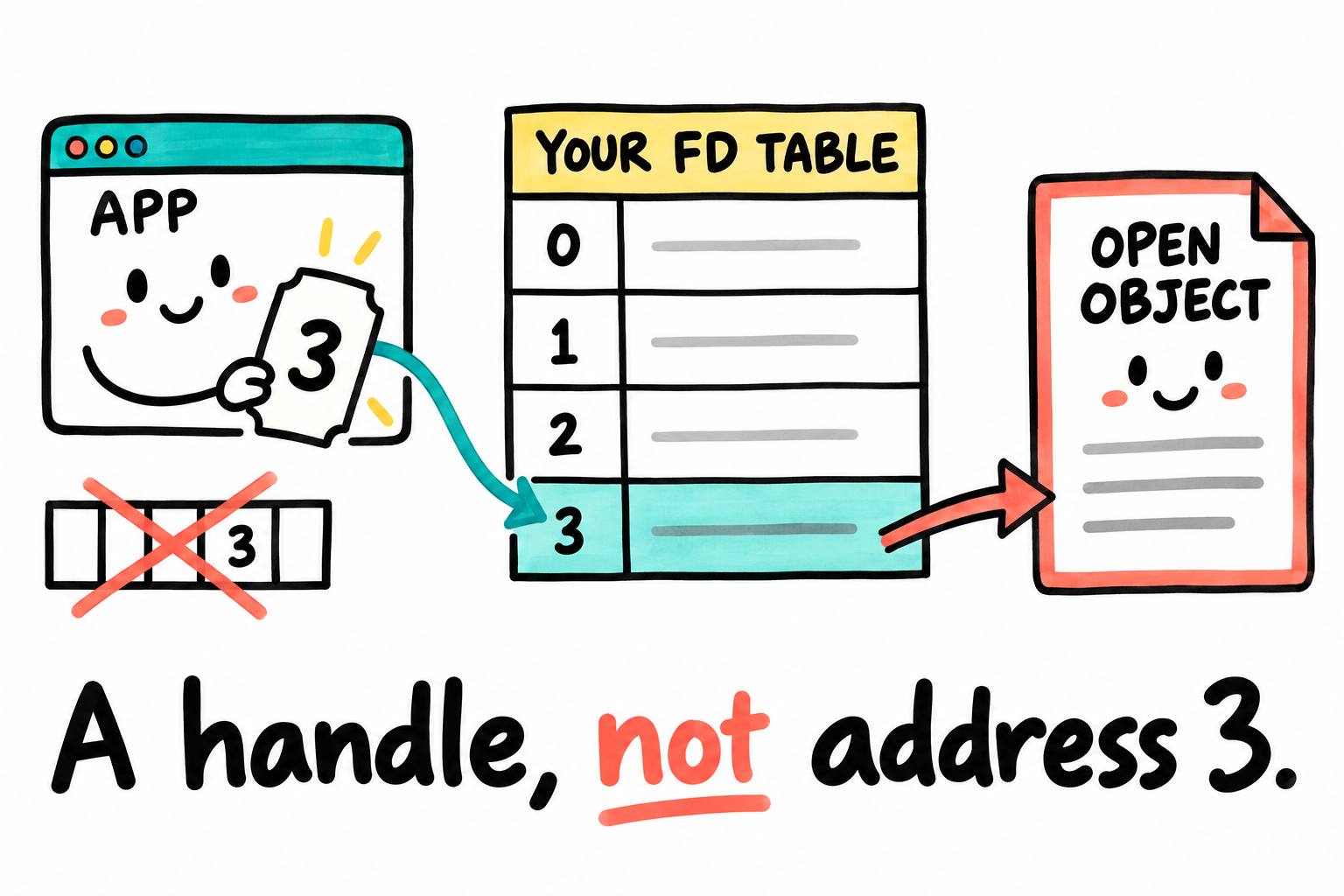
The number is a ticket into a table, not the object itself. The kernel manages that table for the process. Two unrelated processes can both have fd 3 for different open objects. Copying that number alone does not transfer the descriptor.
Later calls such as read(fd, ...) tell the kernel which open object to use. That object may be a regular file, a socket, a pipe, or a device. Other descriptor-creating APIs, including socket(), pipe(), and eventfd(), can wait until we need them.
An open() through the C library returns -1 on failure and sets errno to describe the error. Do not use that result as a valid descriptor. On success, keep the fd while using the object, then call close(fd) to release that reference. The number can be reused for a later open; other descriptors may still refer to the original open object.
By convention, fd 0 is stdin, 1 is stdout, and 2 is stderr. An open gets the lowest free number, even 0, 1, or 2 if its old descriptor was closed. Stdout can lead to a terminal, a file, or a pipe; it is not permanently wired to a UART.
This common handle explains the phrase “everything is a file.” The phrase is not literally true, but many interfaces use the same read(), write(), and ioctl() model. A serial port and a text file behave differently, yet an application can refer to each through an fd.
syscall, libc, glibc, musl
The C functions in your application are not the kernel itself. libc, the user-space C library, implements standard C facilities and wraps many syscalls in ordinary function calls. Glibc and musl are two implementations we will encounter. The syscall underneath is the numbered kernel operation invoked through svc on this board.
When you call printf() from a C program, the path is roughly as follows. The VFS named here is the kernel’s common file-I/O interface; its filesystem details are in the optional reading at the end.
printf("hi\n")
   → glibc formats the string into a buffer
   → glibc calls write(1, buf, 3)
       → glibc's write() wrapper places 1, buf, 3 into registers
       → executes svc #0 with syscall number for write
           → kernel exception handler
               → sys_write()
                   → VFS layer
                       → tty driver's write callback
                           → UART register access
This is a simplified path when stdout is a UART terminal. Buffering and the selected libc can change the calls. The libc and kernel implementations are available as source; Chapter 28 follows kernel startup, while the driver chapters explain device operations.
Process tree, init
Who starts the first application? The kernel runs the selected init program, commonly /sbin/init on a mounted root filesystem or /init in an initramfs, a small initial filesystem unpacked into RAM. It becomes PID 1 and starts the ordinary user-space process tree. Kernel threads have a different origin.
BusyBox init and systemd are two possible init implementations, but the first experiment can be much smaller. In Chapter 29, our statically-linked PID 1 prints a message and deliberately reboots. It must not simply return from main(): the system’s PID 1 exiting causes a kernel panic.
Kernel module (LKM)
A driver does not always have to be built into the kernel image. A kernel module stores kernel code in a separate .ko file that can be loaded while the system is running. insmod foo.ko loads it; rmmod foo unloads it when unloading is permitted.
The .ko suffix can make a module look like one more program file, but loading it puts its code inside the kernel. A faulty module can damage the whole system; it does not get an application’s private-memory protection simply because it was loaded separately. We begin working with modules in Chapter 36.
2.7 Linux storage and memory use
All these layers raise a fair MCU-engineer question: does this small board need the memory budget of a desktop? A desktop installation includes many programs our board will not need. An embedded system selects the kernel features, libraries, and applications for its particular job. The useful comparison is between those selected pieces, not between the board and your entire PC installation.
There is no single “Linux memory budget” to copy into a design. The table locates the costs we will later measure; it is not an additive size estimate. Build options, compression, stripped/debug files, and the workload change the numbers.
Component |
Resource |
What determines the cost |
|---|---|---|
|
Stored compressed boot file |
Kernel configuration and compression |
Running kernel |
RAM |
Loaded sections, kernel allocations, and workload; these categories can overlap |
Device tree blob |
Stored input file |
Hardware description and included nodes |
BusyBox |
Stored executable |
Selected applets, libc, and static versus shared linking |
libc |
Stored library or code linked into executables |
Implementation, ABI, build options, and stripping |
Root filesystem |
Stored tree/archive/filesystem |
Programs, libraries, configuration, compression, and filesystem overhead |
Running user space |
RAM |
Processes, private/shared mappings, and working data |
The MINI core used here has 512 MiB of DRAM. That gives us room to learn without treating the first build as a size contest. A smaller product needs measurements of its actual image, boot-time peak, and running workload, not a sum of unrelated example ranges.
User-space libraries and frameworks can use more storage than the kernel. Common examples are glibc, the C++ runtime, Qt, and Python. This is why Yocto and Buildroot spend much of their work selecting and packaging user-space components.
2.8 What the rest of this book builds, in order
The following table shows the first major stages of the book and where each artifact belongs in the four-layer model.
Chapter range |
Layer |
Artifact |
|---|---|---|
3-8 |
host / 0 / 1 |
Workspace and understanding of Boot ROM and IVT/DCD |
9-17 |
our bare-metal code as a Layer 2 substitute |
LED, DDR, and MMU. Your code performs the bootloader’s early work. |
18 |
optional |
bare-metal I²C/SPI/LCD |
19-24 |
Layer 2 |
U-Boot from source, ported and understood |
25-30 |
Layers 3 and 4 |
Linux kernel and Chapter 29’s first minimal userspace/initramfs |
31-35 |
Layer 4 |
Expand the root filesystem and userspace, then automate with Buildroot |
36-55 |
Layer 3 |
Device drivers and kernel subsystems |
Later parts |
all |
Debugging, product development, build systems, security, and advanced topics |
Return to the four-layer diagram when a later experiment fails. If the Boot ROM has not loaded a valid image, changing an application cannot help. If Linux is running but a device cannot be opened, the image header is probably not the first place to look. The diagram gives us a way to choose the next question.
2.9 Before we move on
We have not configured a GPIO yet, but we can explain why the opening register-writing function cannot simply be carried into a Linux application. Its pointer belongs to a virtual address space, and the physical register is not automatically mapped there. The application normally asks a driver for the operation. A library wrapper, a syscall, and an fd are now recognizable parts of that request rather than three unrelated names.
At the end of the route, someone still writes the GPIO register. Linux has changed who may request it and how the device is shared, not the electrical job of turning on the LED. Keep that distinction. We will return to this same hardware operation when we write bare-metal code and, much later, a Linux driver.
2.10 Key Notes
Boot is a sequence of ownership transfers: the ROM selects and loads an image, the bootloader prepares Linux’s inputs, and the kernel starts user space. Ordinary application requests do not return through the bootloader.
Root credentials affect access policy, not CPU execution mode. A syscall enters a privileged kernel handler and returns the application to user mode with a result or error.
Virtual pointers and file descriptors derive their meaning from the process’s mappings and descriptor table. Equal numbers in unrelated processes need not identify the same bytes or open object.
Drivers own supported hardware operations and resource arbitration. A physical register address alone supplies neither an application mapping nor permission, and separate requests do not automatically form an atomic device protocol.
A minimal root filesystem must supply PID 1 and its runtime dependencies. Static linking can remove the shared-loader requirement, but it does not supply UART support, a console, or permission for PID 1 to exit normally.
Process isolation normally contains an invalid user-space access. Kernel modules run inside the kernel, where a fault can corrupt shared state or stop the system. Deliberately crashing the host is not a safe way to explore that difference.
Stored images, virtual address ranges, and working RAM are different budgets. Their costs depend on the selected kernel, libraries, processes, and workload rather than one universal Linux size.
2.11 Pitfalls
Looking for an “embedded mode” in Linux. We configure the kernel for the target and choose a suitable userspace: perhaps fewer daemons, a smaller libc, and a read-only root. There is no single switch that turns a desktop distribution into the system our board needs.
Treating
bootzas proof of Linux entry. A failed command can return to the U-Boot prompt. After a successful handoff, ordinary U-Boot code is no longer in control; Linux does not use it as a runtime service. Data such as the device tree can remain in memory.Believing
/proc/cpuinfoalways reflects physical hardware. It reports what the kernel detected or was told through the device tree. A virtual machine such as QEMU may report virtual hardware instead.Trying to debug user-space problems with kernel tools and vice versa. Each layer has its own toolset. First identify which layer contains the bug, then choose tools for that layer.
2.12 Going deeper
Names and filesystem objects, optional reference
A filename is how we look something up. Two names can refer to the same object through hard links. An inode is the kernel’s representation of that filesystem object, including its type, permissions, and owner. Directory entries connect names to inodes.
Keep this separate from an open file. An open file object records state such as the current offset, and an fd refers to that open object. How an inode locates content depends on the filesystem; a procfs entry, for instance, need not correspond to blocks on a disk.
An application does not need to ask whether a file is on ext4, FAT, or tmpfs before reading it. The virtual filesystem, or VFS, provides the common kernel interface above those filesystems, as well as procfs and devtmpfs. Each supplies operations the VFS can call. Character and block devices also connect to this framework.
Further reading
The Design of the Unix Operating System, Maurice Bach (1986), for historical background on Unix processes and filesystem design. Its implementation details are not current Linux behavior.
Linux Kernel Development, Robert Love (3rd ed., 2010), for a high-level kernel tour. Compare implementation details with the selected Linux source version.
execve(2), for how an executable file becomes the program image of a running process.
Start with
man 2 intro,man 2 open,man 2 read,man 2 mmap, andman 7 pthreads. See mmap(2) and pthreads(7) for the mapping and shared-resource distinctions above.The Linux source tree’s
Documentation/admin-guide/andDocumentation/process/.
The early examples use a host cross-compiler to produce the board’s programs. Linux can also run a native compiler on a sufficiently equipped target, but that is not our initial route. A compiler name in a host terminal is only a starting point: which compiler file does the shell actually find? Chapter 3 makes that choice visible.