Chapter 22: Porting U-Boot to the MINI
Chapter 19 builds PointAtom’s existing support for the MINI’s core. Why port anything now? Understanding that vendor recipe and maintaining the same hardware on a newer upstream release are different jobs. Ask which settings describe our core, and which describe another carrier or PHY? A successful EVK build cannot answer that question.
Keep two source workspaces. The vendor tree, ~/imx6ull/src/uboot-mini-vendor, is pinned to edb7ca5ac4be2d978be60a2a12c61e0b6d1f7feb with mx6ull_alientek_emmc_defconfig. It is the documented starting recipe for the 512 MiB DDR3L / 8 GB eMMC core shared by ALPHA and MINI. The migration in this chapter uses ~/imx6ull/src/u-boot, based on upstream v2026.04, commit 88dc2788777babfd6322fa655df549a019aa1e69. Old vendor header macros and modern Kconfig APIs are not interchangeable.
The hardware references are the supplied MINI V2.2 carrier and CORE V2.0 schematics. The guide’s PDF pages 7-8 and 236-239 establish shared tutorial/core support; pages 263-283 describe MINI circuits, and Chapter 33 (860-911) explains the original vendor port. Its older LAN8720A procedure is not automatically support for V2.2’s SR8201F. When carrier prose and the supplied schematic disagree, follow the schematic and populated revision.
Port status: This is a concrete, host-buildable modern MINI candidate, not an EVK image with a new name. It implements documented UART1, SD, eight-bit eMMC and ENET2 wiring, with a source-checked SR8201F driver candidate. No board boot, DDR qualification, Ethernet test or media write is claimed. Keep Chapter 19’s vendor UART/storage build as the baseline; replacing a persistent bootloader requires the gates in Section 22.8.
22.1 What “porting” means
On an MCU you compare clock, pad and peripheral tables. Here ordering adds another constraint: ROM initializes DDR from DCD, Device Configuration Data, before full U-Boot runs there. Both selected board paths use ROM+DCD, not SPL.
Create a port ledger in ~/imx6ull/notes/mini-port.md. This is its document-checked starting content, conditional on matching supplied revisions and populated components:
Chain |
Hardware evidence |
Implementation decision |
|---|---|---|
DDR |
Core sheet 3: one NT5CC256M16EP-EK x16 DDR3L, 256M x 16 bits = 512 MiB; sheet 1: |
Compare the published vendor DCD; modern DT reports 512 MiB. Physical qualification remains separate. |
Power |
Core sheet 1 and MINI sheet 4: discrete converters/LDOs, |
No invented EVK PFUZE3000 or GPIO-controlled peripheral rail. Actual rails must be ready before DCD. |
Console |
MINI sheet 4: UART1 TX/RX through analog switches to CH340C and |
UART1 DCE TX/RX, no flow control; kernel example console ttymxc0. |
SD |
MINI sheets 1-2: SD1 CLK/CMD/DATA0-3, CD on |
USDHC1, four bits, active-low CD; no copied EVK |
eMMC |
Core sheet 4: KLM8G1GETF, SD2 CLK/CMD/DATA0-7 on NAND pads; |
USDHC2, eight bits, non-removable, no 1.8 V switching. Vendor |
Ethernet |
MINI sheet 3: one SR8201F, ENET2 RMII, MDIO address 1, reset |
One MAC, with actual PHY-ID/driver matching, not copied Micrel/SMSC assumptions. |
Ethernet clock |
MINI sheet 3: PHY 25 MHz crystal, CLK_CTL pull-up for TXC input, |
SoC supplies the separate 50 MHz RMII reference. Crystal frequency is not RMII reference frequency. |
Optional I/O |
MINI sheets 1-2: LED0 |
Exclude these, display/touch, camera, CAN, Wi-Fi and USB from the minimum boot port. TF and optional SDIO Wi-Fi share USDHC1. |
Inspect actual DDR/eMMC/PHY markings before using this ledger on hardware. A NAND-populated core, another DDR population or an older carrier is a different target. The guide identifies LAN8720A before MINI V2.2 and SR8201F from V2.2 onward, both on ENET2/address 1. An address does not identify a driver.
MINI has one RJ45 despite a copied ALPHA “two interfaces” sentence. On the supplied schematic, KEY0 is connector B48 / UART1_CTS / GPIO1_IO18 with R12 and an active-low switch. SNVS_TAMPER0 is WIFI_REG_ON, not KEY0; GPIO1_IO01 at B49 is GBC_KEY/AP_INT for the ATK module. Do not confuse those three nets. CAN1 uses UART3 CTS/RTS, not the console’s pads.
22.2 The files that connect a board to U-Boot
The vendor support already exists in board/freescale/mx6ull_alientek_emmc/, with include/configs/mx6ull_alientek_emmc.h. Its small defconfig passes an old IMX_CONFIG path through CONFIG_SYS_EXTRA_OPTIONS. In modern v2026.04 the reference is board/nxp/mx6ullevk/, and board Kconfig supplies IMX_CONFIG. Neither path is a universal naming rule.
Our modern local port uses:
board/myorg/mx6ull_pa_mini/
    Kconfig
    Makefile
    mx6ull_pa_mini.c
    imximage.cfg
    MAINTAINERS
include/configs/mx6ull_pa_mini.h
configs/mx6ull_pa_mini_defconfig
arch/arm/dts/imx6ull-pa-mini.dts
arch/arm/dts/imx6ull-pa-mini-u-boot.dtsi
myorg is a teaching namespace, not a registered DT vendor prefix. Underscores name the target/header; hyphens name the DT. A real upstream submission needs an appropriate prefix/binding and actual maintainers.
Source the board Kconfig from arch/arm/mach-imx/mx6/Kconfig and list its DTB in arch/arm/dts/Makefile. This follows the selected reference’s legacy-DTS route, not a silent migration to dts/upstream/.
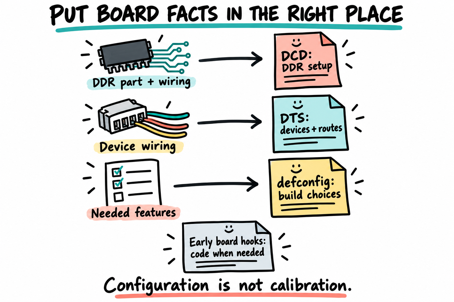
Board facts belong to different files. In this ROM+DCD route, DDR setup must be qualified before U-Boot can use it. A new filename or a successful build does not supply that qualification.
Read the pinned vendor board source beside the modern reference. Carry forward hardware evidence, not every inherited optional hook.
22.3 Step 1, Create the modern MINI target
Work in your own modern checkout. Chapter 21 may already have added commits, so HEAD need not equal the release tag:
$ . ~/imx6ull/scripts/env.sh
$ cd ~/imx6ull/src/u-boot
$ git rev-parse 'v2026.04^{commit}'
$ git merge-base --is-ancestor v2026.04 HEAD
$ echo $?
$ git status --short
$ git log --oneline v2026.04..HEAD
The tag must resolve to 88dc2788777babfd6322fa655df549a019aa1e69; the ancestry check must return zero. The immediately following echo $? reads its silent result. Stop on failure instead of resetting your work. Review extra commits and uncommitted changes too: ancestry establishes the base, not today’s entire source. See Git’s ancestry check.
For destinations that do not already exist:
$ mkdir -p board/myorg
$ cp -a board/nxp/mx6ullevk board/myorg/mx6ull_pa_mini
$ mv board/myorg/mx6ull_pa_mini/mx6ullevk.c board/myorg/mx6ull_pa_mini/mx6ull_pa_mini.c
$ cp include/configs/mx6ullevk.h include/configs/mx6ull_pa_mini.h
$ cp configs/mx6ull_14x14_evk_defconfig configs/mx6ull_pa_mini_defconfig
Inspect existing files rather than overwriting them. The new C file is untracked, so ordinary mv is appropriate. Preserve copied licence/copyright notices. We create the DTS afresh instead of retaining the EVK board include and its unrelated regulators, codec and shift register.
In the board-choice block of arch/arm/mach-imx/mx6/Kconfig, add:
config TARGET_MX6ULL_PA_MINI
    bool "PointAtom MINI V2.2 / eMMC core (migration candidate)"
    depends on MX6ULL
    select BOARD_LATE_INIT
    select DM
    select DM_THERMAL
    select IOMUX_LPSR
    imply CMD_DM
Near its existing board source lines add:
source "board/myorg/mx6ull_pa_mini/Kconfig"
Replace the copied board Kconfig with:
if TARGET_MX6ULL_PA_MINI

config SYS_BOARD
    default "mx6ull_pa_mini"

config SYS_VENDOR
    default "myorg"

config SYS_CONFIG_NAME
    default "mx6ull_pa_mini"

config IMX_CONFIG
    default "board/myorg/mx6ull_pa_mini/imximage.cfg"

endif
In the copied Makefile preserve notices and replace the object line:
obj-y := mx6ull_pa_mini.o
No SPL object is added. Update the inactive PLUGIN path in imximage.cfg to board/myorg/mx6ull_pa_mini/plugin.bin; keep CONFIG_USE_IMXIMG_PLUGIN disabled. Section 22.6 checks the actual DDR sequence rather than leaving copied writes unexplained.
22.4 Step 2, Edit the defconfig and header
Replace the copied defconfig with this complete modern minimum:
CONFIG_ARM=y
CONFIG_ARCH_MX6=y
CONFIG_TEXT_BASE=0x87800000
CONFIG_SYS_MALLOC_LEN=0x1000000
CONFIG_NR_DRAM_BANKS=1
CONFIG_ENV_SIZE=0x2000
CONFIG_MX6ULL=y
CONFIG_TARGET_MX6ULL_PA_MINI=y
CONFIG_DM_GPIO=y
CONFIG_DEFAULT_DEVICE_TREE="imx6ull-pa-mini"
CONFIG_SUPPORT_RAW_INITRD=y
CONFIG_USE_BOOTCOMMAND=y
CONFIG_BOOTCOMMAND=""
CONFIG_BOOTDELAY=-1
CONFIG_SYS_PROMPT="pa-mini=> "
CONFIG_SYS_PBSIZE=532
CONFIG_BOARD_EARLY_INIT_F=y
CONFIG_HUSH_PARSER=y
CONFIG_SYS_MAXARGS=32
CONFIG_CMD_BOOTZ=y
CONFIG_CMD_GPIO=y
CONFIG_CMD_MMC=y
CONFIG_CMD_PART=y
CONFIG_PARTITION_UUIDS=y
CONFIG_CMD_DHCP=y
CONFIG_CMD_PING=y
CONFIG_CMD_CACHE=y
CONFIG_CMD_EXT2=y
CONFIG_CMD_EXT4=y
CONFIG_CMD_FAT=y
CONFIG_CMD_FS_GENERIC=y
CONFIG_OF_CONTROL=y
CONFIG_ENV_IS_NOWHERE=y
CONFIG_BOUNCE_BUFFER=y
CONFIG_FSL_USDHC=y
CONFIG_PHYLIB=y
CONFIG_PHY_REALTEK=y
CONFIG_DM_ETH_PHY=y
CONFIG_FEC_MXC=y
CONFIG_MII=y
CONFIG_PINCTRL=y
CONFIG_PINCTRL_IMX6=y
CONFIG_DM_SERIAL=y
CONFIG_MXC_UART=y
CONFIG_IMX_THERMAL=y
No copied Micrel PHY, QSPI/NAND, SPI shift register, I2C PMIC, video or USB stack remains. CONFIG_PHY_REALTEK is the SR8201F ID-match candidate examined below, not tested networking. Older LAN8720A carriers need their own reviewed driver selection.
Environment changes are RAM-only. ENV_SIZE is capacity, not reserved media. CONFIG_TEXT_BASE is a link address, not a media offset. There is no SPL; FIT/script support is a separate extension in Chapter 23.
Keep the header’s notices and replace its guard/body with:
#ifndef __MX6ULL_PA_MINI_CONFIG_H
#define __MX6ULL_PA_MINI_CONFIG_H

#include <asm/arch/imx-regs.h>
#include <linux/sizes.h>
#include "mx6_common.h"

#define PHYS_SDRAM_SIZE SZ_512M
#define PHYS_SDRAM MMDC0_ARB_BASE_ADDR
#define CFG_SYS_SDRAM_BASE PHYS_SDRAM
#define CFG_SYS_INIT_RAM_ADDR IRAM_BASE_ADDR
#define CFG_SYS_INIT_RAM_SIZE IRAM_SIZE
#define CFG_MXC_UART_BASE UART1_BASE
#define CFG_SYS_FSL_ESDHC_ADDR USDHC2_BASE_ADDR
#define CFG_SYS_FSL_USDHC_NUM 2
#define CFG_FEC_ENET_DEV 1

#define CFG_EXTRA_ENV_SETTINGS \
    "fdtfile=imx6ull-pa-mini.dtb\0" \
    "console=ttymxc0\0"

#endif
CFG_FEC_ENET_DEV=1 names the second FEC hardware instance in our clock hook, not Linux’s interface number. Modern constants use CFG_* where appropriate; the vendor still uses many CONFIG_SYS_* macros. Check their consumers instead of globally renaming symbols.
22.5 Step 3, Describe the actual MINI wiring
This DTS becomes U-Boot’s control FDT, used by driver model. It is not the kernel DTB loaded in Chapter 23. The vendor config instead configures many pads directly in C; its Linux DTB filename does not establish a U-Boot control tree.
Create arch/arm/dts/imx6ull-pa-mini.dts. Include only the SoC description, not imx6ul-14x14-evk.dtsi:
// SPDX-License-Identifier: (GPL-2.0 OR MIT)
/dts-v1/;
#include "imx6ull.dtsi"

/ {
    model = "PointAtom MINI V2.2 with 512MiB eMMC core";
    compatible = "myorg,imx6ull-pa-mini", "fsl,imx6ull";

    aliases {
        /delete-property/ ethernet1;
        ethernet0 = &fec2;
        mmc0 = &usdhc1;
        mmc1 = &usdhc2;
    };
    chosen {
        stdout-path = "serial0:115200n8";
    };
    memory@80000000 {
        device_type = "memory";
        reg = <0x80000000 0x20000000>;
    };
};

&cpu0 {
    clock-frequency = <528000000>;
    /delete-property/ operating-points;
    /delete-property/ fsl,soc-operating-points;
};

&clks {
    assigned-clocks = <&clks IMX6UL_CLK_PLL3_PFD2>;
    assigned-clock-rates = <320000000>;
};

&uart1 {
    pinctrl-names = "default";
    pinctrl-0 = <&pinctrl_uart1>;
    status = "okay";
};

&usdhc1 {
    pinctrl-names = "default";
    pinctrl-0 = <&pinctrl_usdhc1>;
    bus-width = <4>;
    cd-gpios = <&gpio1 19 GPIO_ACTIVE_LOW>;
    no-1-8-v;
    max-frequency = <25000000>;
    status = "okay";
};

&usdhc2 {
    pinctrl-names = "default";
    pinctrl-0 = <&pinctrl_usdhc2>;
    bus-width = <8>;
    non-removable;
    no-1-8-v;
    max-frequency = <25000000>;
    status = "okay";
};

&fec1 {
    status = "disabled";
};

&fec2 {
    pinctrl-names = "default";
    pinctrl-0 = <&pinctrl_enet2 &pinctrl_enet2_reset>;
    phy-mode = "rmii";
    phy-handle = <&mini_phy>;
    phy-reset-gpios = <&gpio5 8 GPIO_ACTIVE_LOW>;
    phy-reset-duration = <100>;
    phy-reset-post-delay = <100>;
    status = "okay";

    mdio {
        #address-cells = <1>;
        #size-cells = <0>;
        mini_phy: ethernet-phy@1 {
            compatible = "ethernet-phy-ieee802.3-c22";
            reg = <1>;
        };
    };
};

&iomuxc {
    pinctrl_uart1: uart1grp {
        fsl,pins = <
            MX6UL_PAD_UART1_TX_DATA__UART1_DCE_TX 0x1b0b1
            MX6UL_PAD_UART1_RX_DATA__UART1_DCE_RX 0x1b0b1
        >;
    };
    pinctrl_usdhc1: usdhc1grp {
        fsl,pins = <
            MX6UL_PAD_SD1_CLK__USDHC1_CLK 0x17059
            MX6UL_PAD_SD1_CMD__USDHC1_CMD 0x17059
            MX6UL_PAD_SD1_DATA0__USDHC1_DATA0 0x17059
            MX6UL_PAD_SD1_DATA1__USDHC1_DATA1 0x17059
            MX6UL_PAD_SD1_DATA2__USDHC1_DATA2 0x17059
            MX6UL_PAD_SD1_DATA3__USDHC1_DATA3 0x17059
            MX6UL_PAD_UART1_RTS_B__GPIO1_IO19 0x1b0b0
        >;
    };
    pinctrl_usdhc2: usdhc2grp {
        fsl,pins = <
            MX6UL_PAD_NAND_RE_B__USDHC2_CLK 0x17059
            MX6UL_PAD_NAND_WE_B__USDHC2_CMD 0x17059
            MX6UL_PAD_NAND_DATA00__USDHC2_DATA0 0x17059
            MX6UL_PAD_NAND_DATA01__USDHC2_DATA1 0x17059
            MX6UL_PAD_NAND_DATA02__USDHC2_DATA2 0x17059
            MX6UL_PAD_NAND_DATA03__USDHC2_DATA3 0x17059
            MX6UL_PAD_NAND_DATA04__USDHC2_DATA4 0x17059
            MX6UL_PAD_NAND_DATA05__USDHC2_DATA5 0x17059
            MX6UL_PAD_NAND_DATA06__USDHC2_DATA6 0x17059
            MX6UL_PAD_NAND_DATA07__USDHC2_DATA7 0x17059
        >;
    };
    pinctrl_enet2: enet2grp {
        fsl,pins = <
            MX6UL_PAD_GPIO1_IO07__ENET2_MDC 0x1b0b0
            MX6UL_PAD_GPIO1_IO06__ENET2_MDIO 0x1b0b0
            MX6UL_PAD_ENET2_RX_EN__ENET2_RX_EN 0x1b0b0
            MX6UL_PAD_ENET2_RX_ER__ENET2_RX_ER 0x1b0b0
            MX6UL_PAD_ENET2_RX_DATA0__ENET2_RDATA00 0x1b0b0
            MX6UL_PAD_ENET2_RX_DATA1__ENET2_RDATA01 0x1b0b0
            MX6UL_PAD_ENET2_TX_EN__ENET2_TX_EN 0x1b0b0
            MX6UL_PAD_ENET2_TX_DATA0__ENET2_TDATA00 0x1b0b0
            MX6UL_PAD_ENET2_TX_DATA1__ENET2_TDATA01 0x1b0b0
            MX6UL_PAD_ENET2_TX_CLK__ENET2_REF_CLK2 0x4001b031
        >;
    };
};

&iomuxc_snvs {
    pinctrl_enet2_reset: enet2resetgrp {
        fsl,pins = <
            MX6ULL_PAD_SNVS_TAMPER8__GPIO5_IO08 0x1b0b0
        >;
    };
};
The 25 MHz storage cap is an initial conservative policy, not a measured maximum. We omit high-speed/UHS modes and voltage switching. The core’s SD1_VSELECT circuit can switch its I/O rail, while the carrier socket remains on 3.3 V; do not request a 1.8 V mode without implementing and validating the complete chain. An already powered rail needs no fabricated switch GPIO.
The SoC include contains generic CPU operating points not established by the core schematic’s MCIMX6Y2CVM05AB label. The override removes those tables and labels 528 MHz; it does not program or qualify CPU clocks/voltage. Check actual silicon and clock setup independently. This control tree is not a production Linux CPU-frequency/power description.
The PHY compatible permits actual MDIO discovery rather than forcing a guessed Micrel/SMSC ID. Reset durations are conservative candidate values, not measured timings. These MAC-node reset properties are consumed by this release’s FEC driver; a property at another location is not automatically equivalent.
Create arch/arm/dts/imx6ull-pa-mini-u-boot.dtsi:
// SPDX-License-Identifier: GPL-2.0+
&pinctrl_uart1 {
    bootph-all;
};
Add this separate line in arch/arm/dts/Makefile:
dtb-$(CONFIG_MX6ULL) += imx6ull-pa-mini.dtb
Optional nodes can follow after their dependencies are reviewed. For example, MINI P4 exposes I2C1 SCL on pin 43 / UART4_TXD and SDA on pin 42 / UART4_RXD, not a guessed adjacent row pair; pin 41 is ENET1_RXER, pin 44 UART5_RXD/I2C2 SDA, pin 45 UART5_TXD/I2C2 SCL. These connectors do not require I2C in the minimum bootloader. Review Linux’s own tree/bindings separately.
22.6 Step 4, DDR config in DCD
There is no spl.c in this target. ROM applies the DCD before entering U-Boot; dram_init() reports the configured memory through imx_ddr_size(), not a new timing initialization.
We have more evidence than “both boards have DDR”: the supplied core shows the x16 512 MiB DDR3L part/rail, and the pinned vendor publishes its initialization recipe. Compare the ordered DATA entries against the copied modern image config:
$ cd ~/imx6ull/src/u-boot
$ diff -u \
    <(awk '$1 == "DATA" {sub(/\r$/, "", $4); print $1, $2, $3, $4}' \
      ../uboot-mini-vendor/board/freescale/mx6ull_alientek_emmc/imximage.cfg) \
    <(awk '$1 == "DATA" {sub(/\r$/, "", $4); print $1, $2, $3, $4}' \
      board/myorg/mx6ull_pa_mini/imximage.cfg)
This is Bash process substitution, run in the Linux shell. It removes a possible Windows carriage return from the final field, but preserves hexadecimal case and entry order. For the pinned inputs, the DATA sequences match. The candidate therefore carries forward the document-compared vendor sequence, not a newly invented calibration table. Keep modern conditional names such as CONFIG_USE_IMXIMG_PLUGIN and CONFIG_IMX_HAB; do not replace the whole file with the old preprocessor wrapper.
Identical bytes establish provenance, not electrical qualification. Confirm populated DDR, core/PCB revision and rail sequencing, then use the matching NXP DDR tooling/test procedure from Chapter 14. Preserve tool/input versions, calibration output and environmental test scope. No measurements of these rails or DDR margins have been performed for this text.
DCD syntax is DATA <width-in-bytes> <register-address> <value>; ordering and initialization commands matter. Review the generated image’s DCD too. A DT memory size cannot repair incorrect initialization. Chapter 20’s PICO SPL study is a different board/architecture, not a MINI substitute.
22.7 Step 5, Board hooks the drivers still need
Why not describe every operation in DT? A binding works only if the selected driver consumes it. This release’s USDHC driver does not call the mmc-pwrseq-emmc implementation. Adding that node alone would leave the reset pulse unexecuted. We use a small hook for NAND_ALE / GPIO4_IO10 instead, following the vendor route without calling it “power.”
Preserve the copied C file’s licence/copyright notices and replace its implementation with:
#include <init.h>
#include <asm/arch/clock.h>
#include <asm/arch/crm_regs.h>
#include <asm/arch/imx-regs.h>
#include <asm/arch/iomux.h>
#include <asm/arch/mx6-pins.h>
#include <asm/arch/sys_proto.h>
#include <asm/global_data.h>
#include <asm/gpio.h>
#include <asm/io.h>
#include <asm/mach-imx/iomux-v3.h>
#include <env.h>
#include <linux/delay.h>
#include <linux/sizes.h>
#include <miiphy.h>
DECLARE_GLOBAL_DATA_PTR;
int dram_init(void)
{
gd->ram_size = imx_ddr_size();
return 0;
}
int board_early_init_f(void)
{
return 0;
}
static int mini_emmc_reset(void)
{
const unsigned int reset = IMX_GPIO_NR(4, 10);
int ret;
imx_iomux_v3_setup_pad(MX6_PAD_NAND_ALE__GPIO4_IO10 |
MUX_PAD_CTRL(0x1b0b0));
ret = gpio_request(reset, "mini-emmc-reset");
if (ret)
return ret;
ret = gpio_direction_output(reset, 0);
if (ret)
return ret;
udelay(500);
ret = gpio_set_value(reset, 1);
if (ret)
return ret;
mdelay(1);
return 0;
}
#ifdef CONFIG_FEC_MXC
static int mini_fec_clock(void)
{
struct iomuxc *regs = (struct iomuxc *)IOMUXC_BASE_ADDR;
int ret;
/* Internal ENET2 reference; REF_CLK2 drives the PHY's TXC input. */
clrsetbits_le32(®s->gpr[1], IOMUX_GPR1_FEC2_MASK,
IOMUX_GPR1_FEC2_CLOCK_MUX1_SEL_MASK);
ret = enable_fec_anatop_clock(CFG_FEC_ENET_DEV, ENET_50MHZ);
if (ret)
return ret;
enable_enet_clk(1);
return 0;
}
int board_phy_config(struct phy_device *phydev)
{
if (phydev->drv->config)
return phydev->drv->config(phydev);
return 0;
}
#endif
int board_init(void)
{
int ret;
gd->bd->bi_boot_params = PHYS_SDRAM + 0x100;
ret = mini_emmc_reset();
if (ret)
return ret;
#ifdef CONFIG_FEC_MXC
return mini_fec_clock();
#else
return 0;
#endif
}
int board_late_init(void)
{
return env_set("board_name", "PA-MINI");
}
int checkboard(void)
{
puts("Board: PointAtom MINI V2.2 migration candidate\n");
return 0;
}
UART1’s pre-relocation pinctrl belongs to the control DT, not a second C pad table. USDHC bus pads also stay in DT; only eMMC reset is owned by this hook. It requests the GPIO, asserts low and releases it, propagating API failures. Assertion follows the vendor’s 500 microseconds, with an initial conservative release delay. Whether the device honors hardware reset also depends on its existing configuration; do not change irreversible eMMC reset-enable fields as a lab shortcut.
ENET2 retains the internal 50 MHz reference path needed by the supplied SR8201F input strap. The PHY’s 25 MHz crystal is a separate circuit. PHY reset belongs to the FEC driver’s DT path, not this C hook.
Check the driver by ID. The CoreChips SR8201F-VB datasheet, register tables 13-14, gives ID words 0x001c and 0xc816, combined 0x001cc816. This matches the v2026.04 RTL8201F entry, UID 0x1cc816/mask 0xffffff. It is a datasheet/source match, not an observed board ID or proof of complete silicon compatibility. Confirm actual suffix/revision and MDIO ID before qualifying the link.
Leave CONFIG_RTL8201F_PHY_S700_RMII_TIMINGS disabled: it chooses another platform’s adjustments. The normal driver uses generic autonegotiation/startup. Real reset recovery, clock direction and packet transfers remain hardware tests.
This board hook removes the inherited unconditional PHY write 0x1f = 0x8190. On SR8201F that address is a page selector, not a universal board register. It returns the selected driver’s config status instead of discarding it. Do not transplant the guide’s LAN8720A global-reset workaround into modern generic PHY code.
The old vendor header enables CONFIG_PHY_SMSC only. That supports its older intended LAN8720A path, not a known-working SR8201F network claim. Generic fallback is not qualification. Chapter 19’s initial example build explicitly disables video and networking, so its inherited display and PHY hooks are not executed. It also disables USB commands to avoid the old USB/network dependency. Any later re-enablement needs carrier-specific review; this modern candidate replaces the inherited PHY write rather than copying it.
22.8 Step 6, Build and inspect the candidate
First build the modern migration in a fresh output directory, without cleaning either source workspace:
$ . ~/imx6ull/scripts/env.sh
$ cd ~/imx6ull/src/u-boot
$ command -v arm-none-linux-gnueabihf-gcc
$ make O="$HOME/imx6ull/build/u-boot-mini-2026.04" \
    ARCH=arm CROSS_COMPILE=arm-none-linux-gnueabihf- mx6ull_pa_mini_defconfig
$ make O="$HOME/imx6ull/build/u-boot-mini-2026.04" \
    ARCH=arm CROSS_COMPILE=arm-none-linux-gnueabihf- -j"$(nproc)"
$ grep -E 'CONFIG_(TARGET_MX6ULL_PA_MINI|IMX_CONFIG|DEFAULT_DEVICE_TREE|TEXT_BASE|ENV_IS_NOWHERE|PHY_REALTEK|SPL)=' \
    ~/imx6ull/build/u-boot-mini-2026.04/.config
$ ls -l ~/imx6ull/build/u-boot-mini-2026.04/u-boot-dtb.imx
$ ~/imx6ull/build/u-boot-mini-2026.04/tools/mkimage -l \
    ~/imx6ull/build/u-boot-mini-2026.04/u-boot-dtb.imx
Keep Chapter 3’s compiler directory name, arm-gnu-toolchain-13.2.Rel1-x86_64-arm-none-linux-gnueabihf, and prefix arm-none-linux-gnueabihf-. No .bashrc/global path edits are needed. Old-source compatibility patches from Chapter 19 belong to the vendor build, not automatically to this release.
Inspect final config, generated arch/arm/dts/imx6ull-pa-mini.dtb, linked board object and image DCD/header. Grep above selects assignments; unset SPL may appear as a comment or be absent. Check actual artifacts too. After menu changes, run make O=... savedefconfig and manually compare its output before updating your source defconfig.
The modern product is u-boot-dtb.imx, distinct from the vendor build’s u-boot.imx. For this modern release’s tools/imximage.c, the non-plugin v2 Load Address label prints the IVT’s BootData pointer, not BootData.start. See the upstream inspection in Chapter 24A Section 21; do not assume the vendor tool displays the same fields. Inspect actual fields to calculate the ROM range.
Flashing is a separate decision. The modern EVK documentation’s 1 KiB SD offset is an EVK-route fact, not a blanket eMMC-area instruction. Compare the modern image’s actual format/length with Chapter 19’s MINI vendor layout evidence. There is no SPL-at-1-KiB / full-U-Boot-at-69-KiB recipe here.
Before a later physical write, establish all of these:
Matching core/carrier population, DCD/power/pad evidence and qualified boot/memory map.
Actual medium/eMMC area, ROM offset, image length, partition map and reserved environment regions, without overlap.
Host device identity, mounts and backup; U-Boot MMC indices are not Linux host device names.
A qualified board-specific recovery image/path without fuse changes.
Reviewed write/read-back procedure, not a copied block count.
No raw write command or target execution is supplied here. A successful build completes the source/API check, not the hardware gate.
22.9 Verify per-peripheral
After the hardware/recovery gate, interrupt autoboot and record real identity. Start with UART/storage; Ethernet is not a prerequisite for reaching the first prompt.
Qualified-board check |
Evidence to record |
Limit |
|---|---|---|
|
Build, reported memory/relocation, active defaults/commands |
Not DDR margin or proof that saved settings fit the new build |
|
SD/eMMC routing and enumerated properties |
Not image-layout/write safety |
Read-only listing/load into reserved RAM |
Prepared filesystem files and load status |
Wrong addresses/sizes can overwrite live RAM |
ENET2 MDIO ID inspection using an actually available command |
Actual address 1/ID, reset/clock evidence and driver |
Management-bus response is not packet communication |
Isolated |
Actual link and transfer results |
Not Linux PHY readiness, NFS-root or reliability qualification |
Normal vendor mapping is MMC 0 for USDHC1/SD and MMC 1 for USDHC2/eMMC. Modern aliases preserve that intent. Still record enumeration: vendor fuse-based mapping and Linux aliases are additional layers, not permission to guess /dev/mmcblkN.
Compare the real PHY ID with Section 22.7, inspect RMII reference/reset if needed, and preserve failure logs. Stop if the observed device differs. A banner saying “FEC” is not a successful network test.
Do not run mtest over a guessed live-DDR range. It can overwrite U-Boot, stack/heap, control FDT or images. DDR qualification uses a dedicated setup with known ownership and a documented test plan.
22.10 MAINTAINERS file
Replace copied EVK ownership. Before submission, fill in actual maintainer details:
MX6ULL_PA_MINI BOARD
M: Your Name <you@example.com>
S: Maintained
F: board/myorg/mx6ull_pa_mini/
F: include/configs/mx6ull_pa_mini.h
F: configs/mx6ull_pa_mini_defconfig
F: arch/arm/dts/imx6ull-pa-mini.dts
F: arch/arm/dts/imx6ull-pa-mini-u-boot.dtsi
This routes review, not certification. Keep hardware revisions, DCD provenance and actual tests beside the port.
22.11 Key Notes
A board port connects build selection, control DT, image configuration and board hooks. A matching SoC target alone does not describe the MINI carrier or populated core.
Ordered vendor DCD writes provide traceable DDR initialization input. The modern DT’s memory size describes a bank but cannot initialize it or establish electrical margins.
DT properties work only through their consumers. In this release, eMMC reset needs the explicit board hook because the USDHC driver does not invoke
mmc-pwrseq-emmc.The single MINI RJ45 uses ENET2. PHY address, PHY ID, 25 MHz crystal and 50 MHz RMII reference describe different interfaces and cannot substitute for one another.
Optional connectors can share pads and controllers. TF/SDIO sharing and the distinct KEY0, Wi-Fi and accessory nets constrain what may be enabled together.
The modern result is a host-built
u-boot-dtb.imxcandidate with RAM-only environment and no SPL. Persistent replacement still requires identified media, a complete range map and a qualified recovery path.
22.12 Pitfalls
ALPHA prose used as MINI wiring. Follow supplied schematics and the populated revision.
Vendor source treated as universal support. Shared core support does not establish the changed carrier PHY.
DCD matching confused with validation. Published-sequence provenance is not measured DDR margin.
Eight-bit eMMC treated as four-bit SD. Include DATA4-7 and the actual reset; do not turn reset into rail control.
Unused DT power-sequence node. Check driver consumers; this USDHC implementation needs the explicit hook.
PHY names/addresses used as driver matches. Compare real ID/mask, then qualify reset/clock/data behavior.
Wrong address space. Link, DCD registers, RAM buffers and media offsets have different purposes.
Saving inherited policy. Modern
ENV_IS_NOWHEREand the vendor’s MMC backend are different; neither permits unreviewed persistent writes.
22.13 Going deeper
Follow the v2026.04 DT control guide, USDHC driver, FEC driver and PHY driver alongside the schematic. Find each property’s consumer before relying on it.
Vendor Chapter 33 explains the original pad/storage/LAN8720A port, but its old symbols, global-PHY workaround and unconditional boot strings are not modern patches. Keep the supplied schematics, matched device datasheets and i.MX6ULL reference manual from Parts I-II beside both trees.
Next chapter: Chapter 23:
bootcmd,bootargs, FIT images. Inspect the vendor storage policy, replace unsafe load chains with explicit gates, and study FIT separately in the modern workspace.