Chapter 19: U-Boot from source, first boot
Our LED program had a modest job. It reached one pin, changed its level, and stayed there. Now imagine extending it until it can find a file on an SD card, read a device tree, choose a boot policy, and start Linux. The register writes would be only a small part of the work.
U-Boot already provides that larger framework. This time, we want its prompt on our Point Atom i.MX6ULL MINI, not a successful build for somebody else’s evaluation board. We will begin with the board vendor’s source, keep its DDR and storage setup visible, and build a deliberately quiet initial image. It will wait for us instead of trying to start an old Linux installation.
The hardware baseline is the supplied MINI V2.2 baseboard with the 512 MiB
DDR3L / 8 GB eMMC core. The core schematic names NT5CC256M16EP-EK memory.
The vendor guide explains that MINI shares ALPHA’s software for the peripherals
present on MINI. That is why an alientek configuration can be the right
starting point even when its filename does not say mini.
Check the markings on your own core and baseboard before following the board steps. A NAND core or another memory arrangement needs its own configuration. Keep the factory image and use a spare SD card first. We have checked the source and host build described here, not performed a physical MINI boot test.
19.1 Start with the MINI’s board support
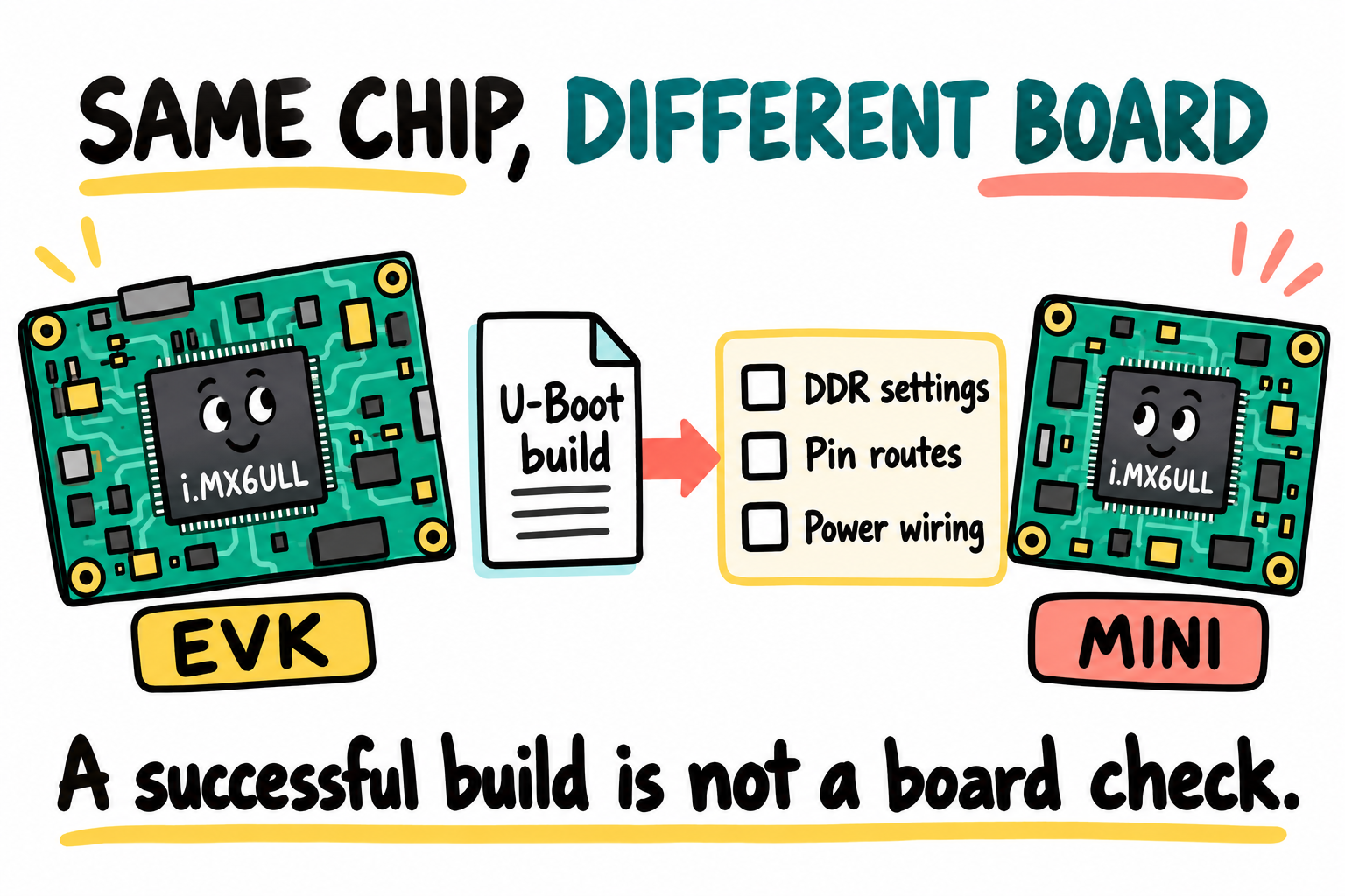
The chip name tells us which SoC logic is shared. The board source supplies the memory and wiring details that the chip name cannot. These drawings are not real board layouts.
There are three useful levels of source:
Source |
What it contributes |
|---|---|
Upstream U-Boot |
The shared project and current frameworks |
NXP’s BSP |
Release-specific support for NXP platforms |
Point Atom’s board source |
The core memory setup and board connections used by the tutorial hardware |
For our first MINI image, use Point Atom’s public tutorial repository
at commit edb7ca5ac4be2d978be60a2a12c61e0b6d1f7feb. It is based on
U-Boot 2016.03. We use this old tree as a board bring-up baseline, not as a
recommendation for a new production product or an Internet-facing recovery
service. It still needs maintenance, security review, and hardware testing.
One naming difference matters. Section 30.2 of the supplied V1.81 guide uses
mx6ull_14x14_ddr512_emmc_defconfig from its factory archive. That name is
not present in this public tutorial snapshot. Here the matching tutorial
target is mx6ull_alientek_emmc_defconfig. Do not combine the archive’s command
with a different source tree, and do not substitute an EVK target just because
it compiles.
Chapters 20-24J also examine upstream v2026.04 in a separate study tree. That newer tree lets us learn current APIs and work through a modern MINI migration. Its EVK and PICO builds are comparisons on the host, not replacement MINI firmware. We will introduce that tree when we need it. For now, one board target and one output directory are enough.
19.2 Clone and look around
Use the lab Ubuntu environment from Chapter 3. $ means the host terminal.
Later, => means the U-Boot prompt on the MINI. Source the environment script
in every new host terminal:
$ . ~/imx6ull/scripts/env.sh
$ cd ~/imx6ull/src
$ git clone https://github.com/alientek-openedv/uboot-imx-rel_imx_4.1.15_2.1.0_ga_alientek.git uboot-mini-vendor
$ cd uboot-mini-vendor
$ git checkout -b mini-first-lab edb7ca5ac4be2d978be60a2a12c61e0b6d1f7feb
$ git rev-parse HEAD
edb7ca5ac4be2d978be60a2a12c61e0b6d1f7feb
The local branch gives our coming edits a home. If the directory already exists, inspect its revision and preserve local changes. Do not clean somebody else’s checkout to make a command match this page.
Open these files in your editor before building:
Path in the vendor snapshot |
Question it answers |
|---|---|
|
Which board target and image configuration are selected? |
|
Which directory and configuration header belong to that target? |
|
How are UART1, SD, eMMC, and the board’s other devices connected? |
|
Which DDR writes does the ROM execute? |
|
What memory size, environment backend, and boot defaults are compiled in? |
|
How does execution enter the shared ARM runtime? |
The old directory name freescale is correct for this snapshot. The newer
upstream tree uses different paths and configuration machinery. Follow the
file in the tree you are actually editing.
Notice that this target does not enable SPL. The ROM executes a DCD, the Device Configuration Data table in the image, to prepare DDR. It then loads full U-Boot into that memory. A missing SPL output will not be a build error.
19.3 A quiet initial image
The factory defaults are intended to boot a complete system. Our initial example needs less: a console prompt, no automatic boot, and no persistent environment changes. We can express that with a small, visible edit.
Open include/configs/mx6ull_alientek_emmc.h. Immediately before its last
#endif, after the Android-support conditional has closed, insert:
/* First MINI lab: stay at the prompt and use a RAM-only environment. */
#undef CONFIG_BOOTDELAY
#define CONFIG_BOOTDELAY -1
#undef CONFIG_ENV_IS_IN_MMC
#define CONFIG_ENV_IS_NOWHERE
-1 disables automatic boot in this release. CONFIG_ENV_IS_NOWHERE selects
the nonpersistent environment backend. Compiled defaults still exist, and
setenv can change their RAM copy, but this build will not load an old MMC
environment or save a new one. We are changing our project, not a host system
file and not the MINI’s eMMC contents.
In that same header, find the #define CONFIG_VIDEO line immediately before
#ifdef CONFIG_VIDEO. Replace only that definition with a comment:
/* Display disabled for the first UART/SD lab. */
#ifdef CONFIG_VIDEO
Leave the enclosed definitions and closing conditionals in place. For this initial console example, no display support is compiled. This matters even without a screen attached: the old display helper drives GPIO5_IO09 as LCD reset, but the supplied core puts that pad in the shared reset network. Chapter 24I examines the mismatch before any display migration. An inherited helper is not permission to pulse the board’s reset line.
Still in the header, find #define CONFIG_CMD_USB immediately before
#ifdef CONFIG_CMD_USB. Replace that definition with:
/* USB host disabled for the first UART/SD lab. */
#ifdef CONFIG_CMD_USB
Again leave the conditional block in place. This old header enables a USB Ethernet adapter driver alongside USB host commands. We disable the whole group before removing networking, rather than leaving unresolved network dependencies. The old header definition would override an unset defconfig entry, so changing only the defconfig would not disable this USB group.
Open configs/mx6ull_alientek_emmc_defconfig and add this line at the end:
# CONFIG_CMD_NET is not set
For this UART/storage example we leave networking and USB host commands out. The header enables
the FEC/PHY code under CONFIG_CMD_NET; disabling it avoids running the old
PHY-specific hook before we have reconciled V2.2’s different PHY. Later
network examples need that support deliberately migrated and tested.
ROM USB recovery is independent of these U-Boot commands and remains available.
There is also a real C lifetime bug in this old source that GCC 13 diagnoses.
Open fs/fat/fat.c and find do_fat_read_at(). Move the declaration
dir_entry dent; from inside its while (isdir) loop to the function’s local
declarations, directly after dir_entry *dentptr = NULL;. Do not leave a second
copy in the loop. The relevant result is:
fsdata *mydata = &datablock;
dir_entry *dentptr = NULL;
dir_entry dent;
The loop stores &dent in dentptr, then code after the loop uses that pointer.
A loop-local dent has already reached the end of its lifetime by then. Moving
the object to function scope keeps it alive through the final file read. We
fix that bug instead of silencing the compiler warning. A downloadable
patch containing these same edits
is available for comparison with your editor changes.
Now build with Chapter 3’s existing Linux-target Arm compiler:
$ make O="$HOME/imx6ull/build/uboot-mini-vendor" ARCH=arm \
    CROSS_COMPILE="$CROSS_COMPILE" mx6ull_alientek_emmc_defconfig
$ make O="$HOME/imx6ull/build/uboot-mini-vendor" ARCH=arm \
    CROSS_COMPILE="$CROSS_COMPILE" -j4
Why repeat CROSS_COMPILE here if the environment script already exported it?
This vendor Makefile assigns an old compiler prefix itself. A command-line
assignment takes precedence over that Makefile assignment. We deliberately
pass the prefix selected by our environment instead of installing another
compiler or renaming a toolchain directory.
U-Boot uses freestanding target build rules, not Linux user-space startup or
glibc. HOSTCC still uses Ubuntu’s native compiler for programs that run on
the host. O= keeps generated files in a separate output directory. Repeat
that same argument on every build command. -j4 allows four parallel jobs.
Use -j1 if the lab machine is short of memory.
This snapshot, including the visible edits above, builds with the book’s Arm GNU 13.2.Rel1 compiler. It produces warnings from old code and assembly, so a successful exit is not a claim of warning-free or production-qualified source. Do not ignore a new error or the dangling-pointer warning we just fixed.
File under |
Use |
|---|---|
|
Target ELF with symbols for inspection and debugging |
|
Linked sections and symbol addresses |
|
Expanded configuration, including old header-defined settings |
|
Main binary without the ROM image wrapper |
|
The ROM-facing image with IVT and vendor DCD |
|
Host image builder used during packaging |
Inspect the beginning of u-boot.imx:
$ xxd -l 32 ~/imx6ull/build/uboot-mini-vendor/u-boot.imx
The IVT starts at file byte zero. Its first four bytes are d1 00 20 40, and
the selected entry address is 0x87800000. Decode the IVT and BootData fields
as in Chapter 7. The old mkimage -l auto-detection can misidentify this image
as a GP header, so do not use that output as proof of an i.MX load address.
This file has no leading 1 KiB pad. Chapter 11’s builder did include one. The media placement must account for that difference exactly once.
19.4 Flash to SD
Our first boot uses a dedicated spare SD card, not an eMMC update. Confirm that the core is the 512 MiB eMMC variant, check Chapter 8’s MINI power and connector procedure, and retain the known-good factory boot path. Do not use these commands with the NAND core or an arbitrary memory replacement.
Location |
Meaning |
|---|---|
Image file byte |
Start of the IVT in |
SD-card byte |
Required location of that IVT on this boot medium |
Raw range at |
Vendor MMC environment layout, if persistent storage is later re-enabled |
Our RAM-only example build does not use that environment region. Still leave the
space reserved: check that the image length plus its 1 KiB placement ends
before 0xC0000, and keep filesystem partitions outside these raw ranges.
A dedicated DOS/MBR example layout differs from GPT, whose primary entries overlap
this boot placement. Do not combine this write with an arbitrary existing
partition table.
Repeat Chapter 11’s card-identification procedure before writing. Confirm
the whole-device path by its size and physical removal/reinsertion, inspect
its mounted partitions, and unmount only the partitions belonging to that
card. /dev/sdX below is a placeholder for the confirmed device. Writing the
wrong destination can destroy another disk’s data.
$ sudo dd if="$HOME/imx6ull/build/uboot-mini-vendor/u-boot.imx" \
    of=/dev/sdX bs=1K seek=1 conv=notrunc,fsync status=progress
bs=1K seek=1 places file byte zero at card byte 1024. There is one image
write, not an SPL write followed by another image at 69 KiB. Do not feed
u-boot.bin to the old imxdownload helper here: it would introduce another
packaging path instead of writing the image we have just inspected.
Read back and compare exactly the written bytes:
$ image="$HOME/imx6ull/build/uboot-mini-vendor/u-boot.imx"
$ bytes=$(stat -c %s "$image")
$ sudo dd if=/dev/sdX bs=1K skip=1 count="$bytes" iflag=count_bytes \
    status=none | cmp -n "$bytes" "$image" -
skip=1 skips 1 KiB. iflag=count_bytes makes count a byte count. cmp
prints nothing and returns success when the bytes match. A mismatch is a stop
point. Matching media bytes establish a correct copy, not tested DDR margins.
19.5 First boot
With board power off, insert the spare card and set the MINI’s documented SD boot switches as established in Chapter 8. Do not use an EVK switch diagram. Remove an optional SDIO Wi-Fi module for this example: MINI shares its USDHC1 signals between that connector and the TF-card socket.
Connect the MINI’s USB-TTL console, not its USB-OTG port. Open the confirmed serial device at 115200 baud, 8 data bits, no parity, and one stop bit before powering the board. The CH340C can enumerate while the core is off, so a host serial device alone does not prove that U-Boot is running.
Our example edit disables the autoboot countdown. If startup reaches the command
interpreter, it should wait at =>. The source’s board banner says
MX6ULL ALIENTEK EMMC. The factory guide shows a different banner from a
different snapshot. Do not require its timestamp, display name, or complete
log to match this build.
Record the actual version output and boot log. A prompt is a useful milestone:
the ROM, vendor DCD, loaded program, runtime, and UART have worked far enough
to answer us. It is not a test of every DDR location, temperature corner, or
peripheral.
There should be no required U-Boot SPL banner for this target. If the board
still counts down or starts the factory Linux image, first check the running
version, switch setting, image placement, and whether our header edit was
compiled. Do not assume you are running the new SD image.
For a silent board, keep the checks in order: power and boot selection, ROM-readable media placement, core-matched DCD, then the console route. A UART change cannot repair DDR setup that prevented entry into U-Boot.
19.6 First commands
Begin with inspection:
=> version
=> help
=> printenv bootcmd bootargs loadaddr fdt_addr fdt_file
=> bdinfo
=> mmc list
version identifies the running program, not the directory on the host.
printenv shows the current RAM environment. Some variables may be absent.
Our initial environment backend does not load saved MMC settings.
The old header can still contain environment strings referring to commands
we disabled. A printed netboot or display variable does not enable that
feature. Do not run the inherited bootcmd in this inspection example.
In bdinfo, record the DRAM start and size, relocation address, and relocation
offset. For the intended core, the declared memory size is 512 MiB starting
at 0x80000000. The startup memory probe is not a full DDR stress test.
The vendor board code maps USDHC1 to U-Boot MMC device 0 (the TF card) and USDHC2 to device 1 (the core’s eMMC). Confirm that with your actual output:
=> mmc dev 0
=> mmc info
=> mmc dev 1
=> mmc info
Selecting and identifying a device does not write its contents. These indices
are not host /dev/sdX names and do not guarantee Linux /dev/mmcblkN ordering.
Do not run mmc write, mmc erase, or saveenv in this first example.
MINI has one RJ45 connector on ENET2. Older baseboards use LAN8720, while
the supplied V2.2 schematic uses SR8201F at PHY address 1. This public tutorial
snapshot selects the SMSC PHY driver, so its build alone does not establish
correct SR8201F initialization. Our initial configuration disables that network
path. Leave Ethernet for the revision-aware checks
in Chapters 22 and 24. A FEC1 log label is a software index, not a second
RJ45 socket that the MINI must have.
md reads memory, but only use an intentionally chosen valid RAM range or a
register whose read behavior you understand. mw and mtest write memory.
They can overwrite U-Boot’s code, stack, heap, device tree, or loaded images.
Do not sweep a large live RAM range with a command copied from another log.
Chapter 14’s memory ownership rules still apply.
19.7 Recognizing Chapter 14 in the ROM’s DCD
Open our vendor target’s board/freescale/mx6ull_alientek_emmc/imximage.cfg.
Two of its MMDC entries are:
DATA 4 0x021B000C 0x676B52F3
DATA 4 0x021B0010 0xB66D0B63
The 4 means a 32-bit write. The addresses select MDCFG0 and MDCFG1.
Their meaning comes from the reference manual and Chapter 14’s DDR timing analysis.
Do not stop at “these numbers also appear in an EVK file.” The provenance
here is the vendor’s board configuration for the documented core, not a
guess made from the SoC name.
The host image builder encodes those textual entries into the DCD. The ROM performs the writes before loading and entering the DDR-resident program. Full U-Boot then establishes its runtime and reports memory. Chapter 24A returns to this same vendor sequence when constructing a teaching port.
The vendor table also enables broad clock-gate masks. That explains its baseline behavior, but it does not make all-ones clock writes a good default for Part II’s smaller experiments. Nor does a vendor table replace testing after changing a DDR part, routing, frequency, or power design.
19.8 Key Notes
The pinned vendor target describes the documented 512 MiB eMMC core. Shared ALPHA/MINI software does not make every carrier connection or PHY revision interchangeable.
ROM executes the image’s DCD before full U-Boot enters DDR. This target has no SPL, and
dram_init()cannot rescue an initializer that prevented execution.The quiet configuration separates console/storage inspection from automatic boot and persistent policy. RAM environment changes do not modify saved MMC settings.
Disabling inherited video, network and USB-host groups prevents unrelated hooks from running before their MINI-specific assumptions are reviewed.
u-boot.imxbegins with its IVT at file byte zero. Its placement at SD byte0x400is a distinct media-layout decision, with boot and environment ranges kept outside partitions.Compilation, image inspection, media readback and a UART prompt establish different boundaries. None alone qualifies DDR margins, every storage sector or Ethernet behavior.
19.9 Pitfalls
A matching SoC is not matching board support. The EVK is a useful comparison, not our first MINI firmware target.
Mixing source snapshots. Factory-archive defconfig names and logs need not exist in the public tutorial snapshot. Follow the pinned tree.
Forgetting the vendor Makefile’s compiler assignment. Pass the environment’s
CROSS_COMPILEexplicitly tomake; do not install another cross compiler.Treating a build as a board test. The source and image checks here do not claim a measured boot or DDR qualification.
Double-wrapping the image. Write the inspected
u-boot.imxat 1 KiB. Do not combine it with a helper that adds another image header or pad.Assuming the PHY never changed. V2.2’s SR8201F needs a revision-aware driver check, even though ENET2 and PHY address 1 remain familiar.
Saving settings to silence a warning. Our initial image is deliberately nonpersistent. Investigate the selected image and backend instead.
19.10 Going deeper
Supplied V1.81 guide: applicability table on pages 7-8, MINI/core description in Sections 5.2.3-5.2.5, MINI schematics in Section 5.4, and U-Boot Chapters 30-33.
Next we ask why some U-Boot images have an SPL and ours does not. Keep the MINI build: it is the concrete result against which we will compare that alternative route.