Chapter 16: Timers, EPIT and GPT
An LED delay loop changes when the compiler changes. A timer lets us ask for an interval without guessing how many instructions the loop takes. We will use GPT1 to read elapsed time and EPIT1 to request periodic service.
The examples require a verified IPG clock, not an assumed 696 MHz CPU. They run in the Chapter 10/15 privileged, MMU-off, integer-only environment and remain in normal run mode. DDR and a higher ARM frequency are not prerequisites.
16.1 Two timers, two jobs
GPT1 counts up freely. We read it for delays and elapsed-time tests.
EPIT1 counts down and reloads. Its compare event requests an IRQ.
A free-running counter and an interrupt source solve different problems: “how much time passed?” and “when should software run?” Linux calls these clocksource and clockevent roles. This is a teaching split, not a claim that every i.MX6ULL Linux configuration uses GPT plus EPIT. The generic timer or a GPT driver may provide those roles, depending on the kernel and device tree.
Use the Chapter 13 audit before initializing these modules. If IPG changes later, stop and reconfigure both timers under the documented procedure; their units are no longer valid.
16.2 GPT, free-running counter
GPT1 base is 0x02098000; the supplied RM describes GPT in Chapter 30.
Register |
Offset |
Role |
|---|---|---|
GPT_CR |
|
Control/source/mode |
GPT_PR |
|
Prescaler |
GPT_SR |
|
Compare/capture/rollover status |
GPT_IR |
|
Interrupt enables |
GPT_OCR1..3 |
|
Output compare |
GPT_ICR1..2 |
|
Input capture |
GPT_CNT |
|
Current counter |
Create timers.h:
#ifndef TIMERS_H
#define TIMERS_H
#include <stdint.h>
int gpt_init(uint32_t ipg_hz);
int epit_init(uint32_t ipg_hz);
uint32_t gpt_now_us(void);
void udelay(uint32_t us);
void mdelay(uint32_t ms);
uint32_t tick_ms(void);
#endif
The following is the first half of timers.c; append section 16.3’s
second half to it. Both initializers return 0 on completion, -1 if their
clock input is unsuitable or reset polling exhausts its budget. That
budget counts software iterations, not calibrated microseconds.
#include "timers.h"
#include "gic.h"
#define REG(a) (*(volatile uint32_t *)(uintptr_t)(a))
#define CCM_CCGR1 0x020C406Cu
#define GPT1_BASE 0x02098000u
#define GPT_CR    (GPT1_BASE + 0x00u)
#define GPT_PR    (GPT1_BASE + 0x04u)
#define GPT_SR    (GPT1_BASE + 0x08u)
#define GPT_IR    (GPT1_BASE + 0x0Cu)
#define GPT_CNT   (GPT1_BASE + 0x24u)

static int wait_clear(uint32_t address, uint32_t mask)
{
    for (uint32_t budget = 1000000u; budget != 0; budget--)
        if (!(REG(address) & mask)) return 0;
    return -1;
}

int gpt_init(uint32_t ipg_hz)
{
    if (ipg_hz == 0 || ipg_hz % 1000000u != 0) return -1;
    uint32_t divisor = ipg_hz / 1000000u;
    if (divisor == 0 || divisor > 4096) return -1;
    /* CCGR1 CG10 bus gate and CG11 serial gate; RUN/WAIT, not STOP. */
    REG(CCM_CCGR1) |= (3u << 20) | (3u << 22);
    REG(GPT_CR) = 0;                    /* EN=0 before source/reset changes */
    REG(GPT_CR) = 1u << 15;             /* SWR */
    if (wait_clear(GPT_CR, 1u << 15)) return -1;
    REG(GPT_IR) = 0;                    /* GPT is polled, no IRQ */
    REG(GPT_SR) = 0x3Fu;                /* W1C all status flags */
    REG(GPT_PR) = divisor - 1u;
    REG(GPT_CR) = (1u << 9)             /* FRR */
                 | (1u << 6)           /* CLKSRC=001: ipg_clk */
                 | (1u << 1)           /* ENMOD: reset on enable */
                 | 1u;                 /* EN */
    __asm__ volatile ("dsb sy" ::: "memory");
    return 0;
}

uint32_t gpt_now_us(void)
{
    return REG(GPT_CNT);
}

void udelay(uint32_t us)
{
    while (us != 0) {
        uint32_t chunk = us > 1000000u ? 1000000u : us;
        uint32_t start = gpt_now_us();
        /* One guard tick avoids returning early due to tick phase. */
        while ((uint32_t)(gpt_now_us() - start) < chunk + 1u) {}
        us -= chunk;
    }
}

void mdelay(uint32_t ms)
{
    while (ms != 0) {
        udelay(1000u);
        ms--;
    }
}
With verified IPG=66 MHz, PR=65 divides by 66, producing 1 MHz.
CLKSRC=001 selects ipg_clk; CLKSRC=010 selects the separate high-frequency
reference/PERCLK path. Do not interchange them.
Unsigned subtraction handles one counter wrap. At 1 MHz, wrap occurs about every 71.58 minutes. Each delay chunk is only one second, but the polling code must still run often enough not to miss a full counter period. It requires a successfully started timer that does not stop during the wait. It has no fallback if that clock disappears.
The unit is nominally one microsecond, not a one-microsecond accuracy
guarantee. Quantization, crystal error, MMIO latency, loop overhead,
and IRQ service add uncertainty. The guard tick favors minimum delay;
udelay(1) repeated a million times will not take exactly one second.
16.3 EPIT, periodic interrupt
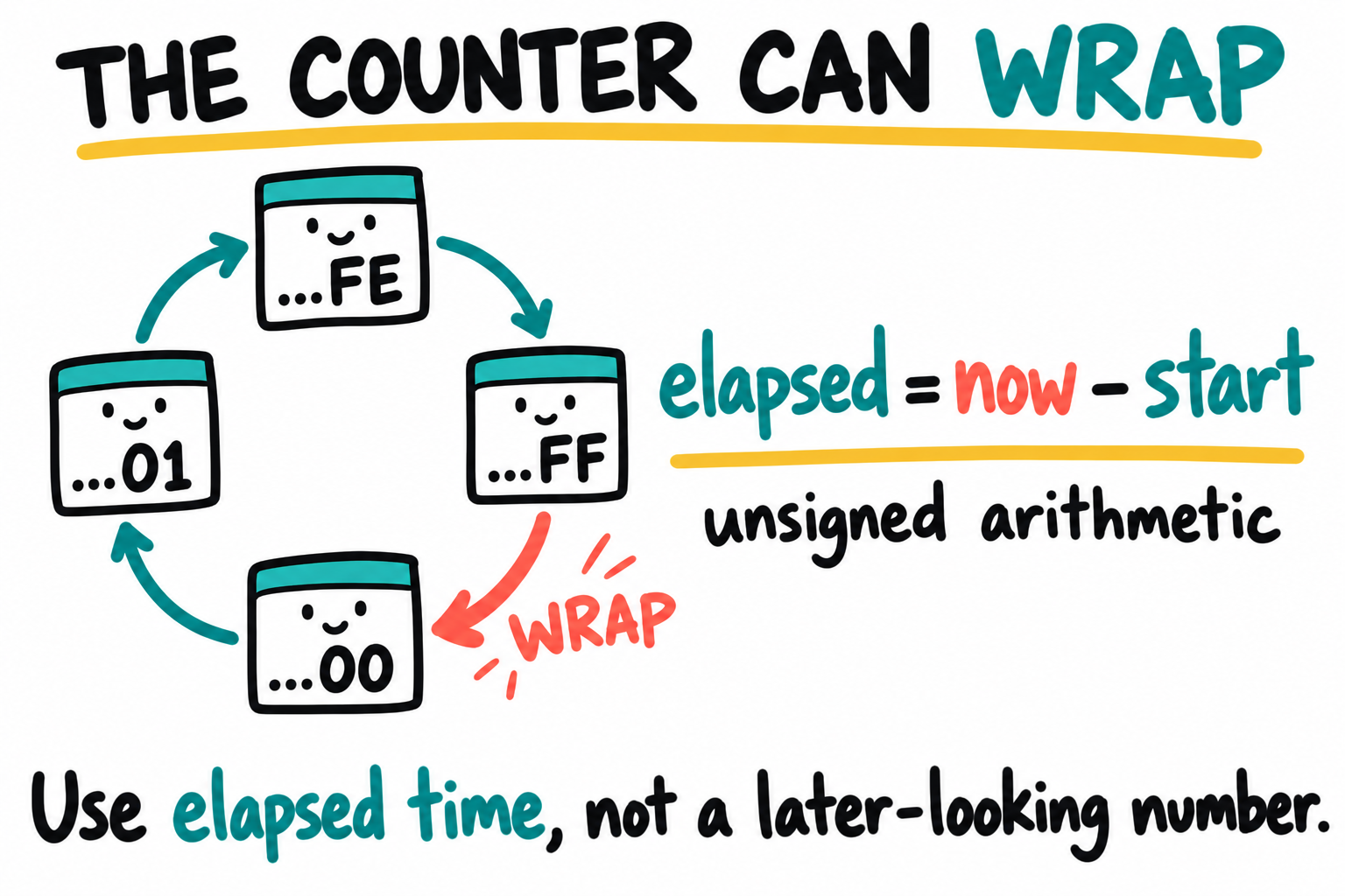
Zero can come after a large count. For a 32-bit timer, the full wrap is from 0xFFFFFFFF to 0x00000000. The drawing abbreviates those digits. Unsigned subtraction works for an interval shorter than one full period, provided we do not miss that period while waiting.
EPIT1 base is 0x020D0000; the supplied RM describes EPIT in Chapter 24.
Register |
Offset |
Role |
|---|---|---|
EPIT_CR |
|
Source/prescaler/reload/control |
EPIT_SR |
|
Compare flag, write-one-to-clear |
EPIT_LR |
|
Reload value |
EPIT_CMPR |
|
Compare value |
EPIT_CNR |
|
Current down-counter |
The steady reload sequence includes zero: with LR=4 it counts
4,3,2,1,0,4,..., five source ticks per period (RM Figure 24-3).
For 66 MHz and 1 kHz, use LR=65999, not 66000, with CMPR=0.
The initial enable-to-first-compare interval has its own starting phase;
measure steady consecutive events when checking the period.
Append this second half of timers.c:
#define EPIT1_BASE 0x020D0000u
#define EPIT_CR    (EPIT1_BASE + 0x00u)
#define EPIT_SR    (EPIT1_BASE + 0x04u)
#define EPIT_LR    (EPIT1_BASE + 0x08u)
#define EPIT_CMPR  (EPIT1_BASE + 0x0Cu)
#define EPIT1_INTID 88u                 /* SPI offset 56 + 32 */
static volatile uint32_t jiffies_ms;

static void epit_isr(void)
{
    REG(EPIT_SR) = 1u;                   /* W1C OCIF; source before EOI */
    jiffies_ms++;
}

int epit_init(uint32_t ipg_hz)
{
    if (ipg_hz < 2000u || ipg_hz % 1000u != 0) return -1;
    /* gic_init() completed; CPU IRQs remain masked during setup. */
    gic_disable_irq(EPIT1_INTID);
    REG(CCM_CCGR1) |= 3u << 12;          /* CG6 */
    REG(EPIT_CR) = 0;
    REG(EPIT_CR) = 1u << 16;             /* SWR */
    if (wait_clear(EPIT_CR, 1u << 16)) return -1;
    uint32_t control = (1u << 24)        /* CLKSRC=01: ipg_clk */
                     | (1u << 3)        /* RLD: reload from LR */
                     | (1u << 2)        /* OCIEN */
                     | (1u << 1);       /* ENMOD: load on enable */
    REG(EPIT_CR) = control;              /* source selected with EN=0 */
    REG(EPIT_LR) = ipg_hz / 1000u - 1u;
    REG(EPIT_CMPR) = 0;
    REG(EPIT_SR) = 1u;
    jiffies_ms = 0;
    gic_register(EPIT1_INTID, epit_isr);
    gic_enable_irq(EPIT1_INTID);
    REG(EPIT_CR) = control | 1u;
    __asm__ volatile ("dsb sy" ::: "memory");
    return 0;
}

uint32_t tick_ms(void)
{
    return jiffies_ms;
}
CLKSRC is bits 25:24; PRESCALER is 15:4 (zero means divide by one). IOVW is bit 17, but this sequence does not need it: ENMOD loads LR on enable. Disabling before changing sources and clearing OCIF are intentional.
The handler is installed before the timer starts and CPU IRQs are enabled last. Chapter 15’s dispatcher performs the barrier before GIC EOI. EPIT’s source is level-sensitive; clearing its flag is not optional.
On this single-core build, the aligned 32-bit volatile read is one single-copy access. It can return the old or new value around an IRQ. It is not a general synchronization primitive. The unsigned count wraps in about 49.71 days; use unsigned differences for short intervals.
More importantly, this counts serviced events, not guaranteed elapsed milliseconds. OCIF is a flag, not a queue: multiple matches while IRQs are blocked can coalesce. A 64-bit version would need a defined update protocol and masked snapshot or sequence counter, not an arbitrary low/high read order.
16.4 Putting it together
This main.c integrates the complete modules with Chapter 12’s UART/printf
and Chapter 15’s vectors/startup/GIC. Add timers.o, clocks.o,
gic.o, and vectors.o to the existing project and preserve its linker
bounds. Use matching integer-only architecture flags when compiling and
linking; put -lgcc after objects. This is not an independent board loader.
No generic clocks_init() is called. The board/ROM configuration must be
approved first; the audit supplies the actual supported IPG rate.
Do not install the UART echo ISR for this example: it would share TX
with foreground printf and lengthen timer latency.
#include "uart.h"
#include "clocks.h"
#include "gic.h"
#include "timers.h"
int printf(const char *fmt, ...);

int main(void)
{
    uart_init();                         /* Chapter 12 root prerequisite */
    uint32_t ipg_hz = clocks_get_ipg_hz();
    gic_init();                          /* leaves CPU IRQs masked */
    if (gpt_init(ipg_hz) || epit_init(ipg_hz)) {
        printf("Timer setup failed; IPG=%u Hz\r\n", ipg_hz);
        for (;;) {}
    }
    irq_enable();
    printf("Timers running; IPG=%u Hz\r\n", ipg_hz);
    uint32_t t0 = gpt_now_us();
    udelay(10000u);
    uint32_t elapsed = gpt_now_us() - t0;
    printf("10 ms request: %u timer us\r\n", elapsed);
    for (uint32_t i = 0;; i++) {
        printf("[%u serviced ticks] heartbeat %u\r\n", tick_ms(), i);
        mdelay(1000u);
    }
}
A representative run would show a delay of at least 10000 nominal timer microseconds, then increasing heartbeat/tick counts. It will not print exact 0/1000/2000 timestamps: setup, the initial delay, UART transmission, and the guarded repeated delays all take time. Measuring a delay with the same GPT validates software behavior, not the oscillator’s absolute accuracy.
If the tick stops, follow the path in order:
Does EPIT_CNR change? Check IPG, CCGR1 CG6, EN and CLKSRC.
Does OCIF become set? Check LR/CMPR and the current count.
Can INTID 88 pass the GIC enable, level, group, target and priority policy?
Are VBAR, IRQ stack, and CPSR.I correct?
Does the handler clear OCIF before EOI? Avoid stopping in the ISR with a breakpoint and interpreting debugger-induced loss as normal timing.
Run mode is deliberate. GPT/EPIT WAITEN/STOPEN and CCM low-power controls are not configured here. Do not add WFI and assume these clocks keep running in every low-power state.
16.5 Profiling with PMU CCNT and GPT
Chapter 13’s PMU fragments explicitly enable CCNT and clear divide-by-64. Keep them in the profiling translation unit or a shared header; do not define the inline reader a second time.
PMU gives CPU cycles; GPT gives nominal microseconds while IPG is unchanged. Changing MMDC alone does not change GPT’s time base. Memory changes can, however, change how many cycles an operation takes.
For an operation lasting well above GPT’s one-tick resolution, use this main-body fragment after both counters are ready:
uint32_t c0 = pmu_ccnt();
uint32_t u0 = gpt_now_us();
/* Perform the operation here; keep all destructive tests in reserved RAM. */
__asm__ volatile ("dsb sy" ::: "memory");
uint32_t c1 = pmu_ccnt();
uint32_t u1 = gpt_now_us();
printf("%u CPU cycles across %u nominal us\r\n", c1 - c0, u1 - u0);
Keep the interval below one CCNT wrap at the actual frequency. Endpoint reads are not simultaneous; measure their overhead, repeat runs, and state whether interrupts/cache effects are included. A long-run cycles-per-microsecond ratio can cross-check the decoded ARM/IPG ratio, but both may share the same oscillator, so it is not independent proof of absolute Hz. A mismatch is a question to investigate, not proof that the clock initializer is wrong.
Instruction count alone does not determine memtest throughput or elapsed time. Pipeline behavior, loop instructions, memory, cache and interrupt service all matter. A 1 MHz GPT cannot directly resolve a sub-microsecond interval.
16.6 Key Notes
GPT’s free-running count represents elapsed ticks. EPIT requests periodic service. Their clocksource/clockevent roles separate time measurement from scheduling, without prescribing Linux’s eventual timer selection.
Both initializers depend on a known, stable IPG rate and the selected source encoding. A later clock change invalidates their units until reconfiguration.
EPIT’s repeating reload period includes zero. With 66 MHz IPG, LR=65999 gives 66000 source ticks per period. Its initial phase need not match the interval between steady consecutive events.
OCIF is a flag, not an event queue. Matches can coalesce while IRQs are masked, so
tick_ms()counts serviced interrupts rather than guaranteed elapsed milliseconds. Short ISR work preserves other sources’ service time.Unsigned subtraction crosses rollover for intervals shorter than one full period. From
0xFFFFFFF0to0x00000020the difference is 48 ticks. That arithmetic says nothing about whether a physical timer kept running.A guard tick and polling overhead favor minimum-delay behavior, not exact duration. Low-power clock continuity and a stopped-counter failure path are separate design requirements not supplied by these run-mode delay loops.
PMU cycles and GPT ticks describe different units. Their ratio can check a clock-tree calculation, but a shared oscillator prevents it from being an independent absolute-frequency measurement.
16.7 Pitfalls
Only one GPT gate. CCGR1 CG10 is bus, CG11 serial; EPIT1 is CG6.
IPG vs PERCLK. Source encodings select different roots.
Assumed IPG rate. The divisor must match the audited, stable input.
Reload off by one. The repeating EPIT sequence includes zero.
Missing W1C. OCIF must be cleared at the source before GIC EOI.
Long masked interval. A flag cannot count every missed match.
Delay timer stopped. The polling loop cannot finish without a running counter, even though its wrap arithmetic is correct.
64-bit counter without a protocol. Use a coherent snapshot/update scheme; volatile alone does not prevent a torn multiword read.
Low-power assumptions. Gate encoding 11 excludes STOP; timer and CCM mode controls still determine behavior.
16.8 Going deeper
IMX6ULLRM Chapter 30 (GPT), Chapter 24 (EPIT): source encodings, reset exceptions, low-power controls, and Figure 24-3.
IMX6ULLRM Chapter 18, CCGR1: separate GPT bus/serial gates.
Cortex-A7 TRM, generic timer and performance-monitor chapters: alternative time bases and cycle-counter controls.
Linux
drivers/clocksource/timer-imx-gpt.c: clocksource/clockevent integration; check the actual device tree before assuming it is selected.POSIX
clock_gettime(CLOCK_MONOTONIC): the user-space abstraction, not a direct read of our EPIT software count.
Next chapter: Chapter 17: MMU and caches. Memory attributes and cache maintenance add new requirements to the MMIO and executable-copy paths. Keep this chapter’s explicit memory/cache policy with those examples.