Chapter 8: Hardware bring-up checklist
Put the board on the desk with every cable still disconnected. After several chapters of addresses and registers, we can look at the actual connectors and switch markings those descriptions depend on. The first question is practical: how should this particular revision be connected and powered?
Then we can look for a result that does not require our own program. Chapter 7’s Boot ROM is already in the chip. In the appropriate USB mode, the host should be able to see its downloader interface even though we have not built a bootable SD image. That observation will give us a known connection to return to when a later download fails.
8.1 What we can and cannot prove yet
We have the Ubuntu tools from Chapter 3 and a Point Atom MINI board. The tempting test is to connect everything and wait for a Linux prompt. That would mix too many unanswered questions together: the supply, cables, boot mode, storage image, and software. Separate them first.
Without a program of our own, we can check that:
The board has no obvious physical damage.
An unpowered resistance screen shows no suspected short; this is not proof that every rail is healthy.
The built-in USB-TTL serial bridge appears on the host.
The requested USB switch pattern agrees with the matching schematic.
The i.MX6ULL Boot ROM enumerates as a USB SDP device.
You can identify the SD-card device on the host without guessing.
Each item answers a smaller question than “does the system boot?” A running Linux system, a successful image transfer, and an LED responding to our code are later tests. Keeping them separate lets us recognize real progress without mistaking a working serial bridge for a working target program.
8.2 Unbox and inspect
Set the unpowered board on an anti-static mat and look over both sides. This quiet inspection saves awkward work later: a cable can cover the switch numbering, and a second USB connector can look much like the first. Find the labels while they are still easy to see.
Visible damage. Look at every connector. Are any pins bent? Are any solder joints cracked or incomplete? Are any capacitors discolored? Did any screw hole damage a trace? Reject and return the board if you find serious damage.
Connectors. Locate USB-OTG, the USB-TTL debug port, Ethernet, microSD, the reference MINI’s 48-pin/2x24 P4 expansion header, LCD connector, JTAG, and power input. A similar-looking header on another board need not have a compatible pinout.
Boot-mode selector. Match your PCB revision to the MINI v2.2 schematic. Record switch numbering/ON direction and compare the patterns in Section 8.5. Do not infer positions from mode names alone.
Photograph the top and bottom, including the printed PCB revision and switch numbering. As you identify the boot settings, photograph those too. Later, when the board is under cables, a clear photo is often quicker to consult than turning the whole assembly over.
8.3 Power rails: unpowered checks, then powered measurements
Choose the power arrangement before any cable
There is an important difference between “this board has a 5 V rail” and “this input accepts my 5 V supply.” The MINI v2.2 power sheet (sheet 3, PDF page 4) shows a DC converter, USB_TTL VBUS (VUSB), OTG VBUS circuitry, K1, JP1/VCC3.3, and JP2/VCC5. JP3 belongs to the RS485 signal routing, not this pair of rail headers. DCDC_5V names a rail, not the barrel-input rating. Do not plug in a guessed 5 V/12 V supply.
Use the supplier’s arrangement for your exact baseboard and core revision. Record the input connector, rated voltage/current/polarity, K1 position, and any jumper settings before applying power. Attach the two USB data cables only if that arrangement documents their VBUS paths. If you have only the schematic and cannot establish those details, stop and obtain the matching board power guide; the book does not provide an electrically validated universal jumper recipe.
Connection |
Role |
Power check before attachment |
|---|---|---|
Supplier-approved supply input |
Main board supply in the selected arrangement |
Rating, polarity, selector/jumpers match the guide |
USB-TTL / DEBUG USB |
Host serial bridge |
Cable carries VBUS; determine whether |
USB-OTG |
ROM SDP data link |
Cable also carries VBUS; check the documented OTG isolation/power path |
External TTL adapter, if used |
UART data only |
Correct I/O voltage; VCC disconnected; no powered output driving an unpowered I/O domain |
A USB cable deserves the same attention as a supply cable: it carries power as well as data. The board’s power switch may therefore leave the serial bridge or other circuitry partly powered. When we say cold power cycle, we mean disconnecting the main input and every USB/power-capable adapter, allowing the rails to discharge, then reconnecting in the documented order. Never move power jumpers on a powered board. Simultaneous-input behavior has not been measured here, so the matching board guide remains essential.
Inventory everything attached. For this first check, leave USB_HOST, expansion/LCD/camera/SDIO add-ons, powered probes, and rail-header connections unused. They can introduce supply paths omitted from a simple two-USB picture. A directly connected adapter’s TX/RX can back-power an unpowered target even with VCC disconnected; remove its signal connection unless the exact interface documents safe isolation.
Here a cold cycle means cycling the main boot-power domains. A coin cell may retain SNVS/RTC power if the matching design permits it; that is different from powering every domain down. Do not remove a battery or short rails to discharge them without the documented sequence. If a retained source can feed the circuit being resistance-tested, establish safe isolation first or stop; a partly powered board is not an unpowered resistance test.
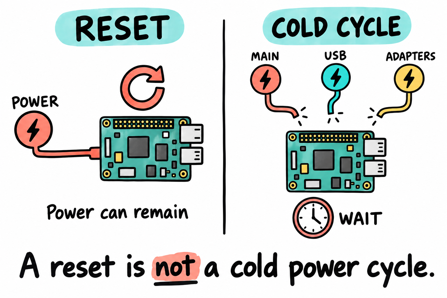
Reset need not remove power. The clock means waiting for the relevant main rails to discharge, not a requirement to erase the backup domain. Follow the board guide’s source inventory and sequence. This generic drawing is not a connector layout or permission to attach several supplies together.
With the power arrangement recorded, make an unpowered resistance check before connecting any cable:
Disconnect all supplies, USB cables, and adapters; allow capacitors to discharge. Use known labeled test points, not guessed adjacent pins.
Select resistance mode and measure 3V3-to-GND, then 5V-to-GND where accessible. Record settled values. A brief continuity beep can be capacitors charging; the beep threshold is meter-dependent.
A persistent near-zero reading suggests a short: stop and investigate. No normal-resistance threshold is specified here without measurements for this revision. A higher reading alone does not certify every rail.
Lift both probes after the resistance check. While the board is still disconnected, put the black lead in COM and the red lead in the voltage/resistance jack, not A/mA, then select an appropriate DC-voltage range. Only then connect the documented supply arrangement. Attach the black probe to known GND and secure it so neither probe can slip across nearby pins. Never measure resistance on a powered circuit.
Now measure:
Probe 3V3 to GND. Expected: about 3.30 V.
Probe 5V to GND if accessible. Expected: about 5 V.
A lit power LED is an observation, not a measurement of every rail. Record the voltages so a later reset or inconsistent result has something to compare against. These accessible rails do not validate core/DDR sequencing or every supply. If a reading is unexpected, disconnect power before investigating.
8.4 Built-in USB-TTL serial console
The debug UART is the connection through which our programs will eventually send text to the host. The MINI already has a USB-to-TTL bridge wired for this purpose, so normal use does not require an external CP2102, CH340, FTDI, or a set of jumper wires.
After Section 8.3’s power-path check, attach USB-TTL/DEBUG USB. It is separate from the USB-OTG port; check the silkscreen.
On Linux, check which serial device appeared:
$ sudo dmesg | tail -20
Look for a message identifying the newly attached serial device, for example:
ch341-uart converter now attached to ttyUSB0
Here the device name is ttyUSB0, so its path is /dev/ttyUSB0. Use the node from your actual attachment log, at 115200 8N1: eight data bits, no parity, one stop bit, and no flow control.
$ sudo picocom -b 115200 /dev/ttyUSB0
If your host reports /dev/ttyACM0, use that instead:
$ sudo picocom -b 115200 /dev/ttyACM0
The terminal opens, but nothing is printed. Should we change the baud rate? Not yet: the Boot ROM prints no UART banner, and we have supplied no printing program. Opening the bridge confirms host access, not target UART configuration. Do not type to wake it up. For the USB-ROM check, quit locally with Ctrl-A then Ctrl-X; plain Ctrl-C can send a character to the board. After a USB unplug/replug, identify the bridge again before reopening it. Chapter 12 gives us our own UART output.
Your board may already contain a factory image in eMMC or NAND. If it prints in its storage mode, keep the output in your notes; there is no need to erase it for this check. If the bridge appears on Windows but not inside an Ubuntu VM, attach it to the guest and close any Windows-side serial session. As in Chapter 3, we use explicit sudo for restricted logs and devices instead of changing host groups.
Unreadable characters later
If you later see unreadable output after our code starts printing, the common causes are:
Wrong baud rate. Use 115200 8N1.
Opening the wrong
/dev/ttyUSBxdevice.Bad USB cable or unstable power.
Return to these checks when a program that should print produces the wrong text. Before we have such a program, silence alone tells us little about the UART.
8.5 Boot-mode selector
Chapter 7 explained that the Boot ROM needs to know where to look for an image. The MINI’s boot selector supplies that choice through the boot-configuration pins. Its four selections are:
Board mode |
What the Boot ROM tries |
When we use it |
|---|---|---|
SD |
Reads a boot image from the microSD card |
Bare-metal examples and removable development images |
eMMC |
Reads a boot image from onboard eMMC |
An installed system on an eMMC board |
NAND |
Reads a boot image from onboard raw NAND flash |
An installed system on a NAND board |
USB |
Requests Serial Downloader mode / Serial Download Protocol (SDP) |
Recovery and early bring-up |
The board normally has either eMMC or NAND fitted, depending on the core-board version. A storage mode cannot boot if that device is not fitted or does not contain a valid image. Record all four switch patterns even if your core board does not contain both storage types.
For the MINI v2.2 schematic’s printed D1-D8 order, its BOOT table gives:
Board selection |
D1 |
D2 |
D3 |
D4 |
D5 |
D6 |
D7 |
D8 |
|---|---|---|---|---|---|---|---|---|
USB |
OFF |
ON |
OFF |
OFF |
OFF |
OFF |
OFF |
OFF |
MicroSD |
ON |
OFF |
OFF |
OFF |
OFF |
OFF |
ON |
OFF |
eMMC |
ON |
OFF |
ON |
OFF |
OFF |
ON |
ON |
OFF |
NAND |
ON |
OFF |
OFF |
OFF |
ON |
OFF |
OFF |
OFF |
Read the row using the switch numbers printed on the PCB, not left-to-right positions in a photograph. Match D1 to switch number 1 and use the printed ON mark; rotating the board does not reverse the numbering. D1/D2 route BOOT_MODE1/0, while the remaining switches configure storage-related straps. USB must result in SoC mode 01; storage selections use Internal Boot with additional configuration.
The table is transcribed from the MINI v2.2 schematic, not hardware-tested for every MINI/ALPHA revision. Check your revision’s routing and the core’s fuse state rather than assuming that every board is unprovisioned and wired alike.
BOOT_MODE0/1 are sampled on POR_B deassertion, its rising edge [RM 8.2.1]. Keep the selector stable through the documented power-up/reset sequence; storage configuration has its own latching details [RM 51.6.3.1]. A software/SRC warm reset is not a board power cycle. A physical button’s effect depends on its routing, so do not classify it solely from the word RESET. Change selectors with the main boot-power domains unpowered, following Section 8.3.
8.6 Confirm USB mode and SDP enumeration
The UART can be quiet while USB tells us something useful. The ROM’s downloader interface does not wait for us to install a Linux image or configure our own UART. Follow the power checks and USB-mode sequence below, then look for its USB identity on the host.
Use a Bash host shell, not the terminal currently owned by picocom. In a newly opened Ubuntu terminal, run . ~/imx6ull/scripts/env.sh and require a successful status before using $IMX6ULL_HOME. Keep target UART receive quiet: no keystrokes, break signal, automated serial probing, or other sender during this ROM USB test. A UART data-ready event can select UART SDP [RM 8.9.2].
Disconnect all sources for a cold cycle as in Section 8.3.
Set the boot-mode switch to USB mode.
Verify the power-guide arrangement permits the USB-OTG cable’s VBUS connection.
Reconnect the documented power/USB arrangement with the switch already set.
On the host, run:
$ lsusb | grep 15a2
Expected output:
Bus 001 Device 008: ID 15a2:0080 Freescale Semiconductor, Inc. i.MX 6ULL in Serial Downloader Mode
The bus and device numbers may change, and the descriptive text can vary. Look for 15a2:0080, the vendor/product identity of the i.MX6ULL ROM downloader. It tells us that the host can see the ROM’s SDP interface.
It does not prove that the selector alone caused entry: fuse settings or fallback from a failed storage boot can also reach SDP. Record the requested switch pattern and observed identity separately. No fuse changes or unvalidated boot-register reads are needed here.
You can also ask uuu to list visible i.MX devices:
$ sudo "$IMX6ULL_HOME/build/mfgtools/uuu/uuu" -lsusb
If your actual output shows that identity, one of our questions has an answer: the host can see the ROM interface without a Linux image running on the board. Keep that output. It does not yet prove image transfer, authentication, or entry-point execution. Chapter 9 will add a different kind of evidence: the LED’s response to our program.
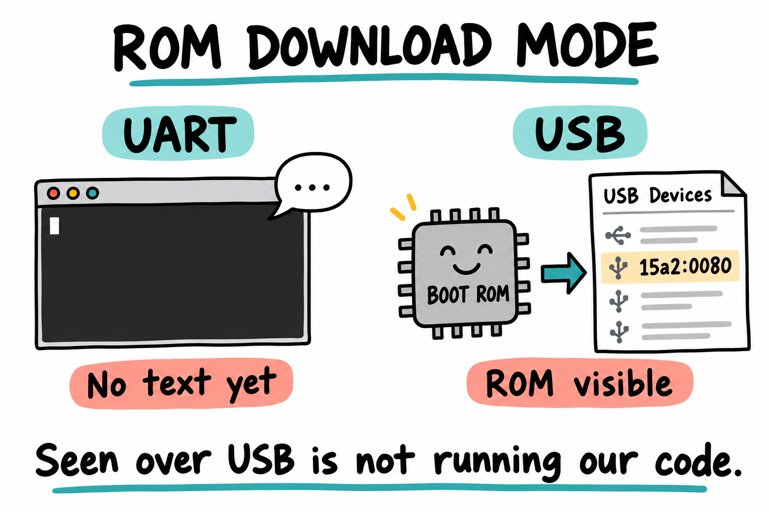
No text yet, but not no information. In the documented USB-mode cold-start state, 15a2:0080 tells us the host sees the ROM downloader. It does not prove a transfer, successful authentication, or execution of our image. These are two observations, not a cable or power-connection diagram.
If you do not see 15a2:0080:
Confirm the boot switch is in the USB position.
Confirm you are using the USB-OTG port, not the USB-TTL debug port.
Try another USB data cable.
Return to the full documented cold-start sequence with USB already selected and UART input quiet; a reset-button press is not a substitute.
Check
sudo dmesgfor USB errors and, in a VM, confirm the ROM device is attached to Ubuntu rather than Windows.
8.7 Prepare the SD-card workflow
USB downloading will let us try the first program without preparing a boot card. In Chapter 11 we will use SD boot too. Before we reach the write command, learn how your host names the card and how to distinguish it from the host’s own disks.
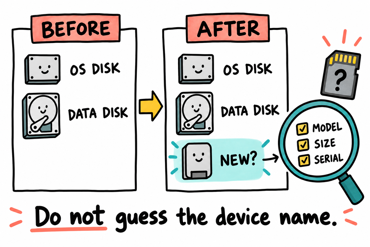
A new row is a question, not a write target. Model/serial fields may describe the USB reader rather than the inserted card. Match the physical spare card to the current whole-disk device using the connection, media/size changes, and before/after output. Missing or ambiguous identity is a reason to stop, not invent a serial number.
With the card not yet inserted, record a baseline; then insert the physical spare card, allow enumeration to finish, and repeat:
$ lsblk -o NAME,PATH,SIZE,MODEL,SERIAL,TRAN,RM,TYPE,MOUNTPOINTS
Read the PATH, TYPE, and MOUNTPOINTS columns in your actual output. For a card observed as /dev/sdc, the whole card is that disk row, not a part row such as /dev/sdc1. This is an example name, not a promised result.
Record the capacity, available identity fields, physical card, reader connection, and current device name. USB model/serial/by-id can identify the reader rather than uniquely identifying the medium; record unavailable fields as unavailable. An empty reader may remain listed, so insertion can change its size/media/partitions without creating a new disk row. If the first listing is incomplete, wait and repeat it. Device names can change; re-identify before every write.
An illustrative tree might look like this; these names are not destinations to copy:
NAME     PATH       SIZE TYPE MOUNTPOINTS
sda      /dev/sda   512G disk
  sda1   /dev/sda1  512G part /
sdc      /dev/sdc    16G disk
  sdc1   /dev/sdc1   16G part /media/you/CARD
Reject sda: its child contains the running system. sdc is only a candidate until its identity matches the physical spare card. sdc1 is a partition, and its mount point must be cleared before removal or a raw write. Native cards can instead appear as /dev/mmcblkN with /dev/mmcblkNp1 partitions. Neither a disk letter nor RM=1 proves safety.
Do not run dd casually. A wrong device name can erase your host disk. Before every SD write in this book:
Take the before-insertion snapshot. If the known card is already inserted and must be removed for comparison, close its users and successfully unmount all its mounted partitions before removal. Stop on a busy/error result; do not force or lazily unmount it.
Insert the card, wait for discovery, and take the second
lsblksnapshot.Match the physical card and current media/size/identity clues; reject disks containing the host system, swap, or unrelated data.
Before a later raw write, close users, successfully unmount every mounted card partition, and recheck that all its mount points are empty. Revalidate its identity immediately before writing.
Write only a known image using its reviewed layout and a freshly identified medium. Stop on any write error. Successful
syncis not proof that a failed write completed, nor a substitute for successful unmounting before removal.
Host enumeration and device identification are not an I/O, sustained-capacity, or write/readback test. Chapter 11 explains an actual boot image and its placement. Reading that explanation does not require writing a card.
8.8 What uuu will do later
uuu can list devices or talk to the Boot ROM over SDP to send an image. With the board in USB mode, an image transfer has this shape once a suitable led.imx exists:
$ sudo "$IMX6ULL_HOME/build/mfgtools/uuu/uuu" led.imx
For our early OCRAM image, the operation has two stages:
Sends an image file over USB-OTG into OCRAM.
Tells the Boot ROM to jump to the image entry point.
The two stages connect our earlier work. The bytes cross the USB connection checked here; the header from Chapter 7 tells the ROM how to handle the image. The code at the entry address must then do something observable. That last part belongs to the next experiment, not to seeing a USB device in the list.
You may encounter MfgTool in older board instructions. It is NXP’s older Windows manufacturing GUI. We use uuu throughout this book, so there is only one downloader to set up and follow.
8.9 JTAG, optional but useful
If the LED does not blink, being able to stop the CPU and inspect its registers can save a great deal of guessing. That is what a JTAG debugger adds: hardware breakpoints, single-stepping, and register inspection. It is optional for Part II. The early examples use observable LED behavior, uuu and serial output to explain different levels of evidence.
Locate the JTAG header now. The important signals are:
TMS
TCK
TDI
TDO
nTRST
RESET
GND
3V3 sense
When selecting an optional adapter, verify its exact model, voltage, target support, cable/pinout, and licensing:
An OpenOCD-supported JTAG adapter may use FT2232H; an arbitrary FT2232H board is not automatically a compatible probe.
J-Link models differ. EDU licensing is educational/non-profit, not a general work-use entitlement; check the exact SEGGER model and terms. A commercially licensed model still needs compatible target/voltage support.
We set up the debugger in JTAG/OpenOCD/GDB. The signals above are functions to verify, not a pin-ordered wiring list. Optional/reset components may be unpopulated. For now, locate the header only; voltage sense is normally a reference input, not permission to power the board from a probe.
8.10 Ethernet, only a physical check for now
The MINI’s Ethernet connector is easy to inspect now, even though IP networking will wait until U-Boot and Linux are running. This check is optional:
With the approved board power arrangement, connect the Ethernet cable to a powered host/switch link partner. Do not assume PoE powering is supported.
Confirm the connector fits firmly.
Observe whether the link LED lights.
A link indication is not proof of IP configuration, packet transfers, or running Linux. A dark LED is not yet a board-failure diagnosis: the PHY may need software setup. Actual networking tests come later.
8.11 What connection evidence establishes
Evidence |
What it establishes |
What remains separate |
|---|---|---|
Base/core revision and matching guide |
Which documented connections apply |
Whether the fitted board matches those assumptions |
Reviewed supply, selectors and USB power paths |
A specific intended power arrangement |
Electrical behavior under load and safe test limits |
Resistance screening and accessible rail readings |
Limited observations at stated points |
Complete rail, reset and sequencing qualification |
Identified serial bridge and opened port |
A host serial channel |
Target code execution or correctly configured UART output |
Observed ROM VID:PID |
A reachable ROM interface |
Image acceptance, execution or DDR health |
Fresh removable-medium identification |
Which host path currently belongs to the card |
Capacity, durability and successful image readback |
These are different evidence boundaries, not a completion worksheet. A physical transfer still requires its actual board, artifact and connection prerequisites. JTAG and Ethernet are optional to that first USB-loaded example.
8.12 Key Notes
Bring-up evidence belongs to a particular board revision, fitted core and power arrangement. A matching product name is not enough to transfer another board’s connector, voltage or selector assumptions.
USB-TTL provides a serial channel, while USB-OTG can expose the ROM downloader. ROM USB enumeration proves that connection in the selected boot mode, not that our image executes or that DDR is healthy.
Power, reset, transport and software are separate failure boundaries. UART silence before a valid program runs is normal and does not identify which boundary failed.
An unpowered short check is only screening. Powered rail measurements need documented test points, limits and a safe supply arrangement, including every possible USB power path.
Removable storage identity must be established again before a write. A device name recorded earlier is not durable evidence that the same card still owns that host path.
8.13 Pitfalls
Confusing USB-TTL with USB-OTG. USB-TTL is the serial console. USB-OTG is the Boot ROM recovery path. They are different functions and may be different connectors.
Expecting serial output too early. With no valid image, silence is normal. The Boot ROM does not print progress messages on the debug UART.
Changing boot switches while powered. Follow Section 8.3’s source inventory and cold-cycle procedure. BOOT_MODE pins are sampled at POR_B deassertion; an arbitrary warm reset is not a substitute.
Using a charge-only USB cable. The board may power up but never enumerate. Use a data cable.
Writing to the wrong SD device. Always compare
lsblkbefore and after inserting the card.Assuming a data cable cannot supply power. USB-TTL and OTG carry VBUS. Use only the revision-specific documented combination; unplug all supply paths for a real cold cycle.
Assuming Ethernet is broken because no link LED appears. Full Ethernet testing waits until software configures the PHY.
8.14 Going deeper
The Point Atom MINI schematic. Print the pages for power, boot mode, USB-OTG, USB-TTL, and SD card.
IMX6ULLHDG, i.MX6ULL Hardware Development Guide, in NXP’s documentation catalog. It is a SoC guide, not the MINI barrel-supply specification.
The
uuuREADME at https://github.com/nxp-imx/mfgtools.An oscilloscope is optional for the checks here. Select probes/bandwidth for a later specific signal measurement; a generic scope rating does not certify DDR or every interface.
Chapter 9 follows a small assembly program from source to a visible LED change. The interesting connection is between compiler output, the ROM image header, the CPU’s entry conditions and a GPIO owner. The board can demonstrate that connection, but the design can be followed without running the example.